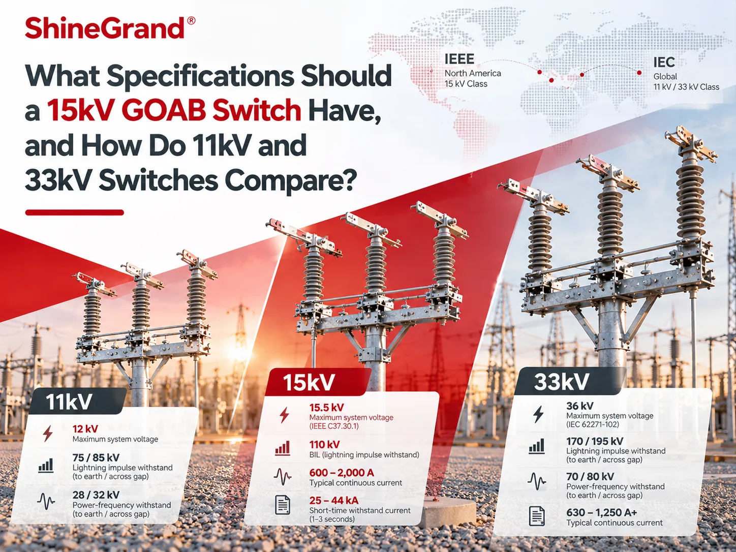
Once you have an understanding of what a gang-operated air break switch is, the next logical question is practical – what ratings to use when making a purchase order. The 15 kV GOAB switch is the most popular rating used in the North America distribution system, but this same feeder may involve other types of switches dealing with 11 kV and 33 kV in different parts of the world. The capabilities of these ratings are not the same according to IEEE and IEC standards. Hence, the information below contains the necessary translation of these tables into numbers. It explains the meaning of each rating of the 15KV GOAB switch, gives some details about the ratings used by utilities, as well as some other aspects when talking about 11kV or 33kV systems.
What are the typical specifications of a 15kV GOAB switch? A GOAB switch having 15 kV characteristics is usually specified for the maximum system voltage equal to 15.5 kV and lightning impulse withstand (BIL) amounting to 110 kV according to the IEEE C37.30.1. Continuous current ratings involve several values like 600 A, 900 A, and 1,200 A for distribution switches along with 2,000 A and more for substation ones. Short time withstand ratings are approximately equal to 25 kA for 600 A uses and even higher for larger ones.
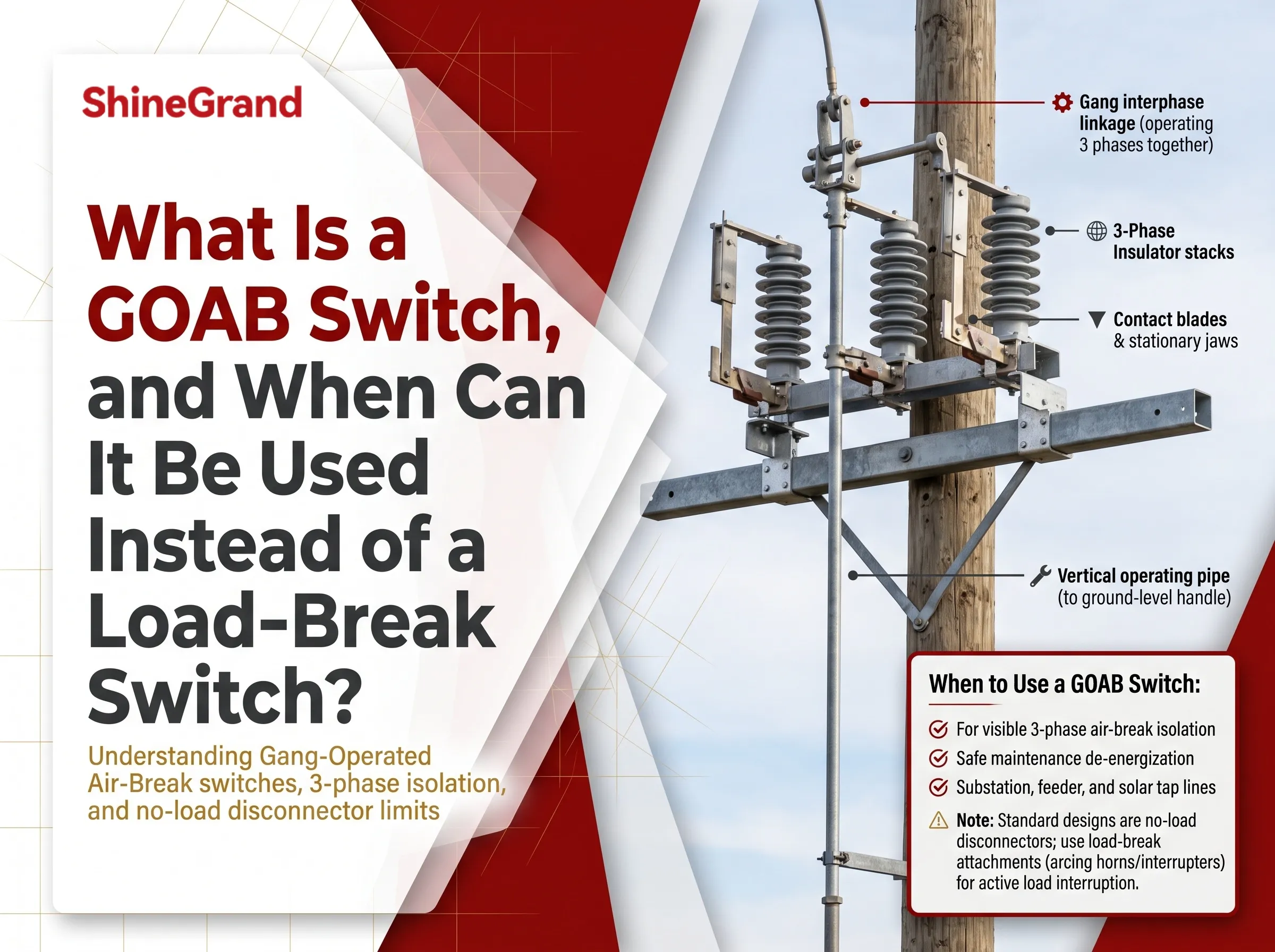
If you are new to these switches, start with ShineGrand’s main guide, What Is a GOAB Switch, which explains the mechanism, configurations and the difference between no-load and load-break designs. This article focuses only on ratings and voltage classes.
What “15 kV” Actually Stands for in a GOAB Switch
The term “15 kV” refers to the voltage class, which is distinct from the system voltage and from the actual rating. IEEE C37.30.1, the American standard for outdoor air switches, defines the 15 kV class switch as one with a rated maximum voltage of 15.5 kV. This allows it to fit in widely known distribution systems of 12.47 kV and 13.2 kV as well as 13.8 kV systems with operating voltages not exceeding 15.5 kV.
The voltage class defines simultaneously three factors: the lowest insulation rating, the distance from the blade to the jaw in the open gap, and the minimal distance separating the phases. This is the reason why a 15 kV switch cannot be used with a 25 kV or a 34.5 kV system even if it is rated for the current.
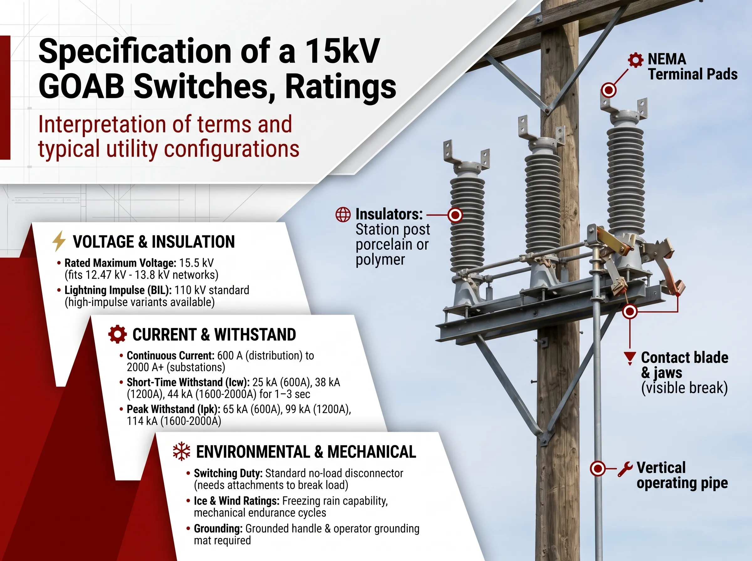
Specification of a 15kV GOAB Switches, Ratings
The following is the interpretation of terms present in the data sheets of the 15 kV GOAB Switch, along with ratings that utility companies usually set.
Rated maximum voltage: 15.5 kV
This indicates the maximum voltage that can occur in the switch during its operation. It will be equal to or greater than the maximum voltage in the system.
The lightning impulse withstand (BIL): 110 kV
According to IEEE C37.30.1, BIL will be 110kV for the 15.5 kV class, which is the maximum voltage of the usual lightning impulse that it has to sustain. Some utilities may specify a BIL of more than this standard, which depends on the incidence of lightning in the locality and if these switches are able to coordinate with the switches working with much higher BIL.
The maximum continuous current: 600 A to 2000 A and beyond
This rating indicates the maximum current that can be conducted by the switch for an indefinite duration without causing any risks. In the case of 15kV GOAB,
The ratings of 600A are suitable for distribution line sectionalising and tie-switches
The rating of 900A and 1200A is used for bypass switches.1,200 A, 1,600 A, 2,000 A and 3,000 A are standard in substations, for instance on transformer secondaries and bus connections.
Select a rating with margin above the highest possible continuous load and planned expansion. Note that load on a tie switch has sudden rise in case of its use for transferring loads from one feeder to another.
Short-time withstand current and peak withstand
In the event of failure downstream of a closed switch, the latter has to withstand the fault current until being cleared by a circuit breaker or recloser without blowing its blades open, welding or being deformed. According to IEEE C37.30.1 the standard current ratings is matched with withstand ratings. The most common variants are:
600 A switches: 25 kA short-time withstand, 65 kA peak withstand at 60 Hertz.
1,200 A switches: 38 kA short-time withstand, 99 kA peak.
1,600 A and 2,000 A switches: 44 kA short-time withstand, 114 kA peak (63 kA / 164 kA available for heavier variants of 2,000 A type).
Always refer to the duration mentioned together with the short-time rating. Manufacturers and technical specifications often refer to either 1 second or 3 seconds, while 4 seconds is very frequently found in terms of the switches to Chinese standards. A rating of 25 kA for 1 second and 25 kA for 3 seconds is not equal.
The value to be specified is obtained from the fault study, which means that the switch short-time rating must be more than the fault current available at that location.
Switching duty: no-load or load break
The conventional 15 kV GOAB is only rated for carrying current not interrupting it. If the switch has to break currents, specifications need to specify what that is: transformer magnetizing currents, line charging currents, load currents, or loop(s) splitting current with the prescribed values for each of them. An example of 15 kV utility substation specification might be a requirement for a load-break switch, which is capable of interrupting the flow of electricity of its 2,000 A load.
Ice and mechanical ratings
Outdoor switches retain the capability to operate under adverse circumstances such as freezing rain. Utility specifications generally require switches to be able to operate under a layer of ice of a specified thickness. Other specifications include terminal loads, wind loads, maximum force required for one person to operate them, and mechanical endurance given in operational cycles.
Insulators, configuration, and mounting
A complete specification for a 15 kV GOAB will also define:
insulator type and creepage: station post insulators with porcelain or polymer insulating material, with creepage defined according to pollution level
break type: vertical break, side break, center break, or double break
mounting: upright on a crossarm, vertical on a pole, or on a substation structure with sufficiently long crossarm and phase spacing
terminal pads: material and coating, and hole pattern, tin-plated copper with a 4-hole NEMA pad
operating mechanism: swing handle, crank or worm-gear manual operator, or motor operator with an auxiliary contact for SCADA
grounding: grounded handle, operator grounding mat, and where required, interlocked earthing blades.
Usual Ratings in IEEE Voltage Classes
This concept is still true for other voltages as well. Outdoor air switch types in power distribution and sub-transmission versions are registered in IEEE C37.30.1 which presents an account of this voltage and impulse strengths.
Maximum voltage of 8.3 kV is equipped by 95kV BIL.
Maximum voltage of 15.5 kV is equipped by 110 kV BIL and it belongs to 15 kV class.
Maximum voltage of 25.8 kV is equipped by 150 kV BIL which is used by 24.9 kV and similar system (the so-called 25 kV or 27 kV class).
Maximum voltage of 38 kV is equipped by 200 kB BIL which is used by 34.5 kV system.
Maximum value of 48.3 kV and 72.5 kV has also the value of 250 kV BIL that is useful for sub-transmission system.
Sometimes producers provide a set of features above all minimum levels so pay attention to a data sheet instead of guessing.
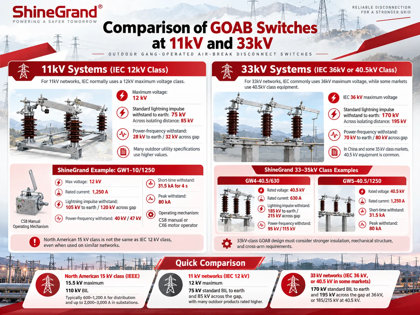
Comparison of GOAB Switches at 11kV and 33kV
Outside North America, the networks operate primarily at 11 kV, 22 kV, and 33 kV, whereby the switches are made as per the IEC 62271-102 or the certain available national standards such as the GB Standards in China. The voltage ratings of the categories follow the standards of insulation as given in IEC 62271-1 while the ratings in this case are different from those included in the tables of IEEE.
11kV systems
A network operating at this voltage class has the maximum voltage of 12 kV, leading to the rating of the switch at 12 kV according to the IEC standards. The most important factor here is that the IEC has the separate withstand basis to earth, and a different one to the isolating distance. As per the applicable 12 kV standard, there are common figures of 75 kV lightning impulse withstanding and 85 kV withstanding to the isolating distance and power-frequency withstands of 28 kV and 32 kV respectfully. However, there are a number of utility organizations and manufacturers which stipulate the higher voltage for their outdoor switches.
Here is an example of the ShineGrand’s GW1-10/1250 outdoor disconnector being used for the indicated 10 kV-11 kV class systems. Its maximum rating is equal to 12 kV and the main rated current equaled to 1,250 A, including those being 105 kV lightning impulse withstand to ground and 120 kV across the gap along with 40 kV for and 47 kV power-frequency withstand values. The whole thing works for the main connectivity of the disconnector for 4 seconds with 80 kA peak withstand. The operating mechanism comes in the CS8 series variant or the CX6 motor operator.
Being said, it is worth mentioning that North America operates at GOAB 15 kV while IEC specifies GOAB at 12 kV for the very same networks. Thus, although on the plant model the level of 15 kV can be equal to 12 kV, it does not mean that much experience does not need the required specification in each case.
33kV systems
In case of 33 kV networks under IEC, the maximum voltage is as much as 36 kV. Thus, according to IEC here at that time the insulation level is approximately 170 kV lightning impulses to earth and 195 kV measured across the isolating distance with the 70 kV and the 80 kV for power-frequency withstand values. In China, the exaction is on the level of 35 kV class voltages, and the level of 40.5 kV using the higher withstand voltages.
ShineGrand Company produces 40.5 kV disconnectors following the 33-35 kV class indicating the following figures:
- GW4-40.5/630: The voltage is equal to 40.5 kV, 630 A, while the values include 185 kV of lightning impulse of atmosphere and crossed gap along with 185 kV with 70 kV withstand value.
- GW5-40.5/1250: The figures presented here serve the purpose of 31.5 kA on the main knife, with 80 kA peak withstand shown in the same way as previously described.
Finally, when talking about the comparison with 15 kV, it is possible to note that the GOAB system must be made considering a whole range of different factors affecting the structure known as cross-arms and electrical resistance of the material.
Quick comparison
- North American 15 kV class (IEEE): 15.5 kV maximum, 110 kV BIL, typically 600–1,200 A for distribution and up to 2,000–3,000 A in substations.
- 11 kV networks (IEC 12 kV): 12 kV maximum, 75 kV standard BIL to earth and 85 kV across the gap, with many outdoor products rated higher.
- 33 kV networks (IEC 36 kV, or 40.5 kV in some markets): 170 kV standard BIL to earth and 195 kV across the gap at 36 kV, or 185/215 kV at 40.5 kV.
A Sample 15kV GOAB Specification Checklist
A short list of technical specifications when requesting quotations for a 15kV GOAB switch can minimize the time spent in the bid process.
1. System parameters such as nominal and maximum voltage, frequency and grounding method.
2. Rated maximum voltage and BIL.
3. Maximum continuous current.
4. Short-time current and duration, and peak current ratings.
5. Type of application to determine whether the switch should be able to handle load, magnetizing or charging operations.
6. Configuration of switch, including its attitude, phase spacing and structure.
7. Type of insulator and distance from creepage.
8. Working principle, including type of operation and maximum effort.
9. Whether the device requires an earthing blade and interlocking.
10. Standards applied (IEEE C37.30.1 or IEC 62271-102) and mandatory tests.
Frequently Asked Questions
What is the BIL of a 15kV GOAB switch?
Under IEEE C37.30.1, a 15 kV class outdoor air switch rated 15.5 kV maximum has a standard BIL of 110 kV. Some specifications call for higher impulse levels in lightning-prone areas.
Can a 15kV GOAB switch be used on a 13.8kV system?
Yes. A 13.8 kV system’s maximum operating voltage is below the 15.5 kV rating of a 15 kV class switch, so the voltage class is suitable, provided the current, short-time withstand and insulation requirements also match.
Can I use a 15kV GOAB switch on an 11kV network?
From an electrical standpoint, a switch that has a rating of 15.5 kV is rated accurately for an 11 kV system with a maximum of 12 kV. If however, it is stated in the project specifications that compliance with IEC is required, the switch will have to meet the specified IEC requirements for testing and short-time withstand which may not be the case for a switch tested under IEEE standards. This shall be confirmed from the project specification.
What current rating should I choose for a 15kV GOAB switch?
The rating selected should be higher than the maximum continuous current that the switch is allowed to carry, meaning that some allowances must be given for future needs and loads through tie switches. Usually, for line switches, a rating of about 600 A is sufficient, while it is around 900–1,200 A for the main-line and bypass, and even higher for the substation switch.
What does short-time withstand mean on a disconnect switch?
The term RMS fault current is used to denote the value of the current through the switch having been closed for a specified time duration which is usually given as 1, 3, or 4 seconds. It is important that this value must be bigger than the value of fault current which can occur at the point of installation. The peak withstand value corresponds to the amount of fault current with maximum peak for the time of occurrence.
Is a 15kV GOAB switch load-break rated?
Not unless it is specifically designed and tested for load interruption. A standard 15 kV GOAB is a no-load disconnect. Load-break versions use interrupter attachments or arcing horns with a stated, tested interrupting rating.
References
- IEEE C37.30.1 — Standard Requirements for AC High-Voltage Air Switches Rated Above 1000 V. Preferred voltage, BIL, continuous and withstand ratings for outdoor air switches.
- IEC 62271-1 and IEC 62271-102. Common specifications and requirements for high-voltage disconnectors and earthing switches, including insulation levels.
- Hubbell Power Systems — Air Switch Specification Data. Manufacturer tables of voltage classes, BIL and withstand ratings per ANSI C37.30.1.
- Snohomish County PUD — 15 kV Group-Operated Vertical-Break Load-Break Disconnect Switch Specification. An example of a real utility specification for a 15 kV switch.
- ShineGrand — What Is a GOAB Switch?. Meaning, working principle, configurations and load-break considerations.
Specifying Switches for 11kV, 15kV or 33kV Projects?
Whether you need a 15kV GOAB switch for a North American feeder or an outdoor disconnector for an 11 kV or 33 kV network, the right specification comes down to voltage class, insulation, current, fault withstand and switching duty. ShineGrand supplies the GW series outdoor disconnectors for 10–12 kV and 40.5 kV systems. Send your ratings and mounting requirements to ShineGrand to confirm a suitable configuration.