When you begin your journey into electricity or electronics, you quickly discover one sign: two coils sitting adjacent with a few lines between them. This is a transformer, and understanding how to recognize it is the first step towards reading any schematic. The question arises though: how does an AC transformer symbol is represented on the transformer circuit diagram, what is the meaning of each line? This manual provides simple explanations so you do not need to have any background knowledge in order to understand the role of transformer in a circuit diagram.
As the name suggests, a circuit diagram is just a plane representation where standard signs are used instead of photos of real objects. Instead of drawing a massive metal transformer, the engineers use just a small symbol which is well-known by everyone.
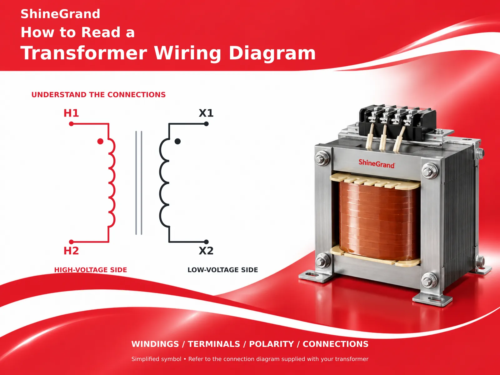
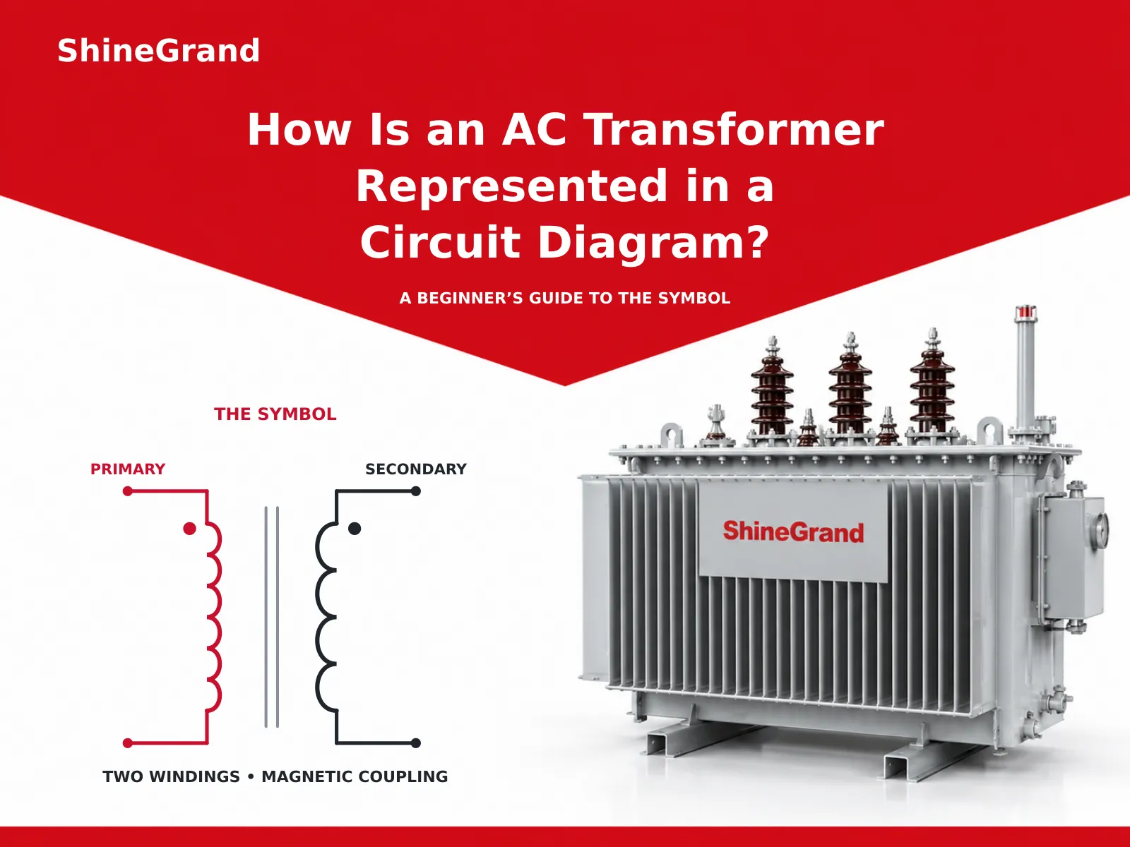
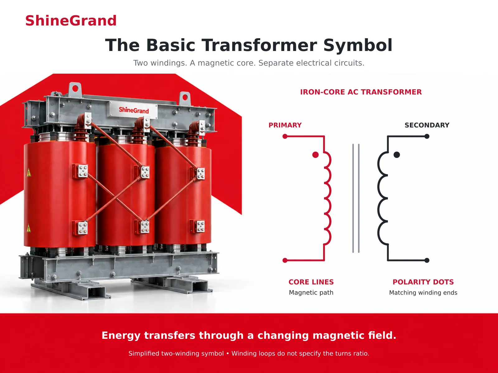
A schematic of a transformer consists of two coils (or windings) adjoining each other to represent primary and secondary coils. The iron core that connects the two coils is shown via one or more vertical lines in between the coils. One side of the transformer connects to the input AC and other side connects to output. Dots placed beside the coils show the polarity. Some indication about the function of the power transformer can be received from the size of the coils and turns-ratio. There is no direct wiring connection between two sides and energy is being transferred through the magnetic field.
What Is a Transformer, in Simple Terms?
Understanding how a transformer operates can provide insight into the symbolism used in its representation. A transformer is a device made to change alternating current (AC) voltage levels. It consists of two coils of wire that are wound around the same iron core. The first one, known as the primary coil, receives the alternating current (AC) supplied into it. The second one, the secondary coil, leaves out the final output. When alternating current flows through the primary, a changing magnetic field is present in the iron core. The clever part is that the two coils cannot touch electrically; therefore, electricity does not flow.
The Basic Transformer Symbol
The common transformer diagram consists of only three elements, and once you know them, you will be able to identify the diagram quickly.
The windings. There are two pieces of wire that are connected to the transformer and are referred to as coils. The first is called the primary coil, and the second one is called the secondary coil.
The core. Now we have to draw the lines that form the core of the transformer. The lines that are drawn vertically and connect the two coils serve to illustrate the magnetic core of the device. The two lines will ensure that the diagram is of a transformer with an iron core.
The terminals. The lines that come out of the coils indicate the terminals where the wires are connected; the terminal for the input voltage is on the primary coil and the terminal for the output voltage is on the secondary coil.
That is the whole basic symbol. When you see two coils separated by two vertical lines in a transformer circuit diagram, you are looking at an iron-core AC transformer.
Why AC and Not DC?
One of the basic questions that people ask when they are first learning about transformers is why they only operate with AC (alternating current). The answer lies within the way they function.
The reason is that for a transformer to generate voltage in the secondary winding, it needs a changing magnetic field. Since AC keeps alternating with time, it is obvious that a changing magnetic field will always be produced. Conversely, a steady flow of direct current (DC) leads to the establishment of a constant magnetic field that does not induce voltage in the secondary once it is formed. This fact explains the reason for being the AC transformer and transformer circuit diagram mostly referring to AC. It can also be seen that the transformer symbol is regularly used in equipment connected to mains power.
Reading the Details: Dots, Turns, and Voltage
Various little details apart from the basic design tell you what job the transformer is performing.
The polarity dots are small dots found at one end of every coil. They indicate which terminals are positive at the same time, and it is important in case the phase difference matters. For a newbie, the main detail is that the dots show the ends of the windings which match with each other.
The turns ratio indicates whether the transformer increases or decreases the voltage level. The transformer works by means of the turns ratio between the two coils when the secondary coil has more turns than the primary coil or vice versa. There are diagrams showing this by drawing a bigger coil or by marking it – for instance, from 240V to 120V or like 2:1.
Variations of the Transformer Symbol
Once you grasp the basic symbol, the rest can be easily interpreted since they are just slight variations of the same shape.
Iron-core transformer. Consists of two windings with both solid lines illustrated. This is the standard design in AC applications and the design you will come across most frequently.
Air-core transformer. Composed of two windings in which there are no connects between them and this model is mostly found in radio frequency applications.
Center-tapped transformer. It has a secondary winding that has an extra link in the middle making it common in power supply systems.
Autotransformer. It consists of a single winding that has a tap in the middle and is not making use of two separate coils while electrical isolation is still needed.
All of these are still clearly transformers; the coil shape is the constant that identifies them in any transformer circuit diagram.
Single-Phase and Three-Phase in a Diagram
Several examples of a beginner transformer circuit include one primary coil and one secondary coil. However, more complex power systems will also contain three-phase transformers, which display three sets of coils connected together in the diagram. The connections may be arranged in a delta shape or a Y shape, as the diagram shows. Although it is not necessary to understand the workings of three-phase systems in order to read a transformer diagram, understanding that three sets of components simply indicate a three-phase transformer system, which operates in a similar way across three different phases, is enough to understand how the transformer system works.
A Beginner’s Step-by-Step: Reading the Transformer in a Schematic
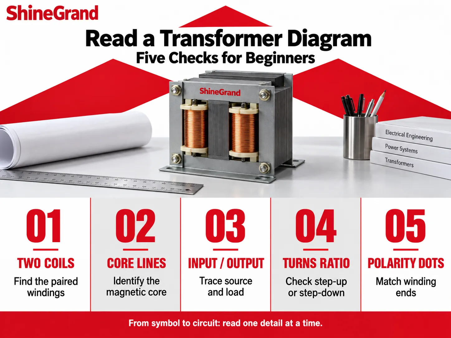
Here is a simple routine for spotting and understanding a transformer the next time you open a transformer circuit diagram. Follow these steps and it becomes second nature.
-
Identify the two coils. Look for the schematic that comprises the two coil shapes placed opposite each other. This combination is the transformer, which can be identified easily once you understand the shape.
Check for the core lines. Look for the lines in between the coils. Two straight lines indicate an iron-core transformer for AC applications, whereas no lines indicate an air-core transformer for high-frequency applications.
Find both primary and secondary winding. Trace the wires for identification. The winding that connects toward the power source is called the Primary while the one that connects toward the load is called Secondary.
Check the voltage ratio. Look for numbers such as 240V and 120V, or for the markings like 2:1. Larger secondary voltage indicates a step-up transformer while smaller means step-down transformer.
Look for the dots, if available. The dots indicate the polar isolating between the windings which holds great importance in advanced electrical circuits but should be checked in the beginning itself.These five checks can reveal how any transformer works and what is the source of power as well as its destination during transmission.
Why the Symbol Matters
Though it may appear minor, a shared symbol is what allows engineers, electricians, and students to understand an electrical schematic in the same way, regardless of where in the world they are. Effective use of electrical circuit diagrams means that the underlying system can be explained without any images or text. This is explained by the idea behind schematic symbols: they take a complicated engineering system and simplify it. The transformer symbol is one of the best examples of a symbol worth learning at the beginning of the journey towards understanding electrical drawings as transformers are used in many circuits, from small chargers to national grids.
From Symbol to Real Equipment
The simple symbol on a schematic stands for a real, physical transformer out in the world. The same primary-and-secondary idea scales all the way from a tiny transformer inside a phone charger to the large units on the power grid. ShineGrand Electric manufactures the real distribution and power transformers that these symbols represent, including the 6-10KV Oil-Immersed Distribution Transformer for medium-voltage networks, the Three Phase Pad Mounted Transformer Series, and the indoor 20-35kV Epoxy Dry-Type Transformer. Each real unit carries a nameplate and diagram that use exactly the symbols and markings described here, so the schematic and the hardware always speak the same language.
Frequently Asked Questions
How does a transformer work in a circuit?
In the circuit of transformer, the primary coil receives the alternating current voltage that generates an alternating magnetic field in the iron core of the transformer. This magnetic field generates an electric voltage in the secondary coil of the transformer, which is the effective output of transformer. The transformers do not have the electrical connection but rather use magnetic field for transmitting the energy from coil to coil. Depending upon the ratio of turns in two coils, the transformers transform the input voltage to either higher or lower voltage, and thus can be referred to as step-up or step-down transformers.
Is a transformer AC or DC?
Transformers fall under AC devices since they operate with oscillating magnetic fields and use induced voltage to generate power in their secondary. When DC is applied the magnetic field remains constant, but it does not induce steady voltage making transformers incompatible with DC. Thus, transformers function only in systems equipped with AC.
How do I wire up a transformer?
The fundamental principle of operation is that incoming AC power connects to the primary terminals and load connects to the secondary terminals as per the equipment diagram and name plate. The equipment diagram shows the respective terminals and voltages; also, for three phases, it shows the configuration whether delta or star. Electric power should be off and locked out before starting wiring; moreover, wiring should be done by qualified electrician for anything other than a small low voltage equipment.
What would burn out a transformer?
Typical reasons consist of overloading (pulling more current than its rating), voltage spikes such as from lightning or switching, short circuits, overheating caused from inadequate cooling and venting and aging or wetness of insulation. All of these lead to overheating or stressing the windings of the transformer until insulation fails. Proper sizing, using protection equipment e.g. fuses and surge arresters and ensuring adequate cooling of the transformer are key to safeguarding it against burnout.
References
- IEC 60617 — Graphical Symbols for Diagrams. The international standard defining electrical schematic symbols, including the transformer.
- IEEE 315 — Graphic Symbols for Electrical and Electronics Diagrams. The reference standard for circuit-diagram symbols used in North America.
- IEC 60076 — Power Transformers. The international standard series covering transformer construction and operation.
- Electrical Engineering Portal. Neutral educational resource on transformer symbols, operation, and circuits.
- Transformer — Wikipedia. General reference on transformer operation, the turns ratio, and schematic symbols.
Reliable Transformers From ShineGrand Electric
Understanding the symbol is the first step; behind every symbol is a real transformer that has to be well made. ShineGrand Electric Co., Ltd. designs and manufactures a complete range of power and distribution transformers, in both oil-immersed and dry-type designs, along with high-voltage fuses, surge arresters, and disconnect switches. Whether you are learning the basics or specifying equipment for a real project, explore our full transformer product range or contact the ShineGrand team to learn more.