
Anyone who either creates or chooses transformers must inevitably perform similar calculations: the turns number, the turns ratio, the wire diameter, the capacity, the current, and losses. To reduce repetitive tasks for the engineer, there is a transformer calculation table that works on the same principles and makes calculations very simple, and fast. This article is about how the transformer calculation table works, what parameters are calculated by this table, what formulas are used in it, and how to create, and apply it in practice, so as to have its guide in engineering.
Whether it is a power transformer for a local substation or a flyback transformer for a switching power supply, the principle is the same. A good table allows making all equations once, thus, after changing such an input as voltage, power, frequency, etc, all other correlated variables will be calculated automatically as well.
In the conclusion, it should be mentioned that a transformer calculation table is a tool built in the form of a table; normally a spreadsheet. It takes care of repetitive calculations in a transformer selection or design process. After entering the necessary values such as voltage, power, frequency, and core information the tool calculates the required turn ratio, wire size, power, and values of losses.
What Is a Transformer Calculation Table?
The transformer calculation table is a mathematical or engineering tool that is primarily a structured package containing values, formulas, and results usually programmed in a spreadsheet. In this setup, instead of calculating each equation each time, engineers put known values into input cells, and based on some pre-defined formulas, they get results calculated automatically.
The beauty of this approach is that it ensures the uniformity of calculations. Since calculations are stored in a table and not on a piece of paper or in someone’s head, every calculation will be done in the same way, using the same assumptions, and can be also verified by other members of the team. Thus, the transformer calculation table allows not only for work efficiency but also is a means of proper education that provides clarity on the results of any calculations made.
Why Use a Transformer Calculation Table?
The main aim of building such tables is to provide automation for routine calculations; however, this is not the only benefit provided by a good calculation table. First of all, the transformer calculation table allows to save time due to the immediate update of results whenever any value changes. Secondly, this table ensures the uniformity of equations applied by all members of the team. Thirdly, it helps to save money because there are no mistake
Key Parameters a Transformer Calculation Table Computes
Though the particulars vary based on the application, generally, most tables are identified by the same parameter families. Thus, it is important to know these parameters when selecting, using or designing a transformer.
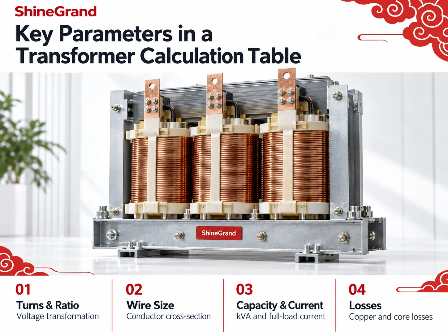
Turns and turns ratio. The number of primary and secondary turns in the transformer and turns ratio.
Wire gauge. The gauge of the wire that is being wound in the transformer depending on current rating.
Capacity. kVA or MVA are expressed for transformer capacity and full load current.
Losses. Losses due to copper in the winds and losses in the core material altogether determine efficiency and heat rise.
Supporting values. Based on the design the table may include core area, flux density, current density and duty cycle.
The Core Formulas Behind the Table
The utility of a transformer calculation table will depend on the formulas it contains. The formula for voltage transformation tells us that the ratio of primary to secondary voltage equals the ratio of primary to secondary turns. The formulas for capacity and for current will depend on whether it is a single phase transformer or a three-phase transformer. In the case of a single-phase transformer, kVA equals volts times amps divided by 1000, while the full load current equals kVA times 1000 divided by voltage. In the case of the three-phase transformer, kVA equals square root of 3 times line voltage times line current, divided by 1000.
Wire size is determined according to current density, where the required area is current divided by the chosen current density in amperes per square millimetre. Losses occur due to two reasons, copper losses and core losses. These simple formulae result in the calculation table being able to use a small number of variables to create a complete picture.
Using a Transformer Calculation Table for Power Transformer Selection
When the goal is to select rather than design a transformer, the transformer calculation table focuses on matching a unit to a load. The engineer starts with a connected load, translates it into a needed kVA, adds a higher value, and then picks a size of transformer as close as possible. A general rule is that a transformer should not be loaded greater than about 80 percent of its capacity. To simplify calculations for choosing a transformer, one can divide the needed kVA value by 0.8 considering 20 percent of future growth as a safety factor. Standard distribution sizes are arranged in increments of 15-30-45-75-112.5-150-225-300-500-750.
This is where the manufacturer’s range of products comes in. After the calculation table gives the kVA requirement and gives the engineer the voltage class and the number of phases, he starts matching it with the equipment available. ShineGrand Electric manufactures a full range of distribution and power transformers to select from, including the 6-10KV Oil-Immersed Distribution Transformer for medium-voltage networks, the high-voltage 110-132kV Oil-Immersed Distribution Transformer for substation duty, the ground-level Three Phase Pad Mounted Transformer Series, and the indoor, fire-safe 20-35kV Epoxy Dry-Type Transformer. The table tells you what you need; the product range provides the unit that meets it.
Using a Transformer Calculation Table for Flyback and SMPS Design
On the opposite extreme of the spectrum, designers of switching power supplies utilize the transformer calculation table to build small high-frequency transformers of the flyback type. In this case, the input and output differ as the transformer is a part of a switching converter and not of the mains distribution system. The table conventionally starts with the input and output voltages, switching frequency, duty cycle, and characteristics of the ferrite core, especially the effective cross-section area and peak flux density of the material.
Using that information, the table computes the quantity of the primary turns needed to handle the volt-seconds applied with every switching cycle, the secondary turns based on outgoing voltage, the wire gauge of each winding based on the current and the current density selected. The core is selected based on the area product, which combines the window area and the cross-section, and it estimates the losses that may happen to ensure that the engineer evaluates temperature rise and efficiency.
alculation Table Step by Step
Making a workable table is simple, provided that it is designed properly. The clear design differentiates between the inputs, calculations, and outputs, so the rationale is easy to follow.
Identify the inputs. List the values with their relevant labels, such as the main voltage, power rating, number of phases, frequency, and core information. Keeping all of the inputs together allows for reuse of the table.
Write the equations down in the calculation cells. It is a good idea to write down the required formulas once in the calculation cells and refer to the inputs for calculating the required values.
Indicate the results. Present the results in a logical manner so that the information is clear and easy to read.
Include standards and checks. Insert reference data and incorporate some sanity checks that would indicate unbelievable results.
Test the developed table by using some previously-known information.
A Worked Example
When it comes to choosing a three-phase transformer suitable for a 100 kVA load at 400 volts, the engineer can use the 80% loading method to determine the required capacity of 100/0.8 = 125 kVA. Thus, the transformer can be specified in a larger class (the closest standard size), i.e. 150 kVA. Evaluating the full-load current on the output (kVA multiplied by 1000 and divided by square root of 3 times the voltage), the final result shows 150,000 divided by roughly 692 being 217 amperes, which determines the cable and protection dimensions. With the help of the transformer calculation table, the input load and voltage allows calculating the above information all at once, while the variations of the load means that the recommendations in terms of the size and currents are calculated at once, as the table keeps the method and numbers change executing the calculations automatically.

Common Mistakes to Avoid
It is necessary to be careful while using a calculation tool. The most common mistake made while using the instrument is to forget to use the square-root-of-three factor and end up mixing single phase with three phase calculations creating errors up to 73 percent. The second issue is unit confusion e.g. using watt rather than the volt-ampere or unit of measurement like millimetres instead of metres. Also, the copper-loss value should be calculated on the basis of operation temperature since the value of the coil’s winding resistance is not constant. Another mistake is not to take the loading margin into account while sizing a transformer exactly according to the load and what is even worse – not to leave some margin. Finally, the table should support engineering judgment but not replace it, i.e the results should be double-checked against the existing norms, manufacturers’ information, and the qualified engineer in case it is needed.
Frequently Asked Questions
How do you calculate a transformer?
To begin the process, one must first determine the load, and then employ the standardized formulas for computing the capacity. For single-phase possibilities, kVA would equal voltage multiplied by amperage, divided by the number of 1000. The picture changes slightly for three-phase calculations, as one must include the square root of three. After determining capacity, it is onwards with full-load current calculation as well as turns ratio based on voltage ratio. A transformer calculation table performs all of these steps automatically.
How much of a 480V to 208V transformer do I need?
This is a three-step selection for reducing capacity. Find out the total connected load in kVA and divide the result by 0.8 to provide a margin of 20 percent, and select the next higher standard size. For instance, a load of 100 kVA becomes 125 kVA when adding the margin, so the transformer of the rating of 150 kVA should be chosen. Confirm the results against the actual load profile and local code.
How many amps is a 300 kVA transformer good for?
The current is dependent on the “voltage”. In three-phase systems, full-load current is given as: kVA times 1,000 divided by the square root of three multiplied by the voltage. A typical 300 kVA transformer will have an output of approximately 833 amperes when plugged into 208 volts and about 361 amperes when connected to 480 volts. Thus, it can be said that when lower voltage is used, the current will be higher for the same kVA.
How do I calculate the kVA of a transformer?
The formula for calculating the kVA of a transformer is the same regardless of its type. However, in the case of a single-phase transformer, units of volt-amperes get easily converted into kilovolt-amperes merely by dividing the volt-amperes by 1000. In the case of a three-phase transformer, its kVA is found by multiplying the square root of 3, 1.732, with the line voltage and the line current and then dividing by 1000. For example, 480 volts and 120 amps in three-phase gives approximately 100 kVA.
References
- IEC 60076 — Power Transformers. The international standard series defining performance, rating, and testing requirements for power transformers.
- IEEE C57.12.00 — General Requirements for Liquid-Immersed Distribution, Power, and Regulating Transformers. Reference standard for transformer ratings and construction.
- IEEE C57.91 — Guide for Loading Mineral-Oil-Immersed Transformers. Guidance on loading limits behind the common 80 percent sizing practice.
- NFPA 70 — National Electrical Code. Reference for transformer protection and conductor sizing, including Article 450.
- Electrical Engineering Portal. Neutral educational resource on transformer calculations and power system fundamentals.
- Transformer — Wikipedia. General reference on the turns ratio, ratings, and transformer operating principles.
Reliable Transformers From ShineGrand Electric
Once your transformer calculation table tells you the rating, voltage, and configuration you need, the next step is matching it to dependable equipment. ShineGrand Electric Co., Ltd. designs and manufactures a complete range of power and distribution transformers, in both oil-immersed and dry-type designs, along with high-voltage fuses, surge arresters, and disconnect switches. Whether you are selecting a unit for a substation, a distribution network, or an industrial facility, explore our full transformer product range or contact the ShineGrand team for expert guidance tailored to your project.