The transformer wiring diagram might seem challenging initially, however, it is no more than a map that indicates the way the windings inside the transformer are connected, provides information about terminals and how to connect the transformer to electricity supply as well as load safely. Just after learning a form of symbols and terminal names, you will clearly understand what used to look like a puzzle.
Whether you are an electrician on the ground, engineer giving specifications regarding the equipment, or technician troubleshooting and fixing the panel, this diagram is the common language. It provides you with information regarding primary and secondary voltage, winding type, polarity and grounding.
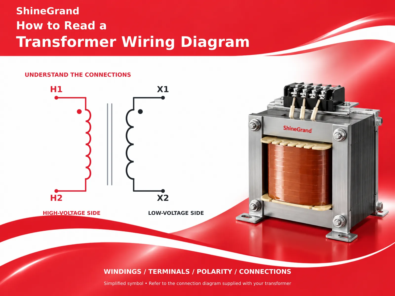
Understanding the transformer wiring diagram is possible because of knowing its basic points. The diagram uses standard symbols for coils and makes use of the letters H and X to designate high and low voltage terminals according to the terminology – primary terminals are labeled H1, H2, etc., and secondary terminals X1, X2, etc. Besides, it preserves the essential indicators for both terminals.
Transformer Basics: What the Diagram Represents
Before discussing the meaning of the symbols, it should be noted what exactly a transformer does. A transformer transfers electrical energy from one circuit to another using electromagnetic induction and consists of two sets of windings – primary and secondary, wound around a single iron core. The incoming electricity reaches the primary and is passed to the secondary where the voltage is transformed. There are no moving parts hence the device relies on the magnetic coupling of the coils. A transformer wiring diagram is simply a visual representation of the windings and their connection shown in universal symbols so that professionals in this field can read it in the same way.
Understanding Terminal Markings: H1, H2, X1, X2
Learning about the terminal marking system is the most important factor in understanding transformer wiring diagrams, since that enables you to distinguish between sides of the transformer. What is important is that the marking system is consistent across various transformers, thus making it easier to operate with different types of transformers.
H terminals (H1, H2, H3, H4) are designed for high voltage, primary side connection; in case of step-down transformers, it means high voltage coming to transformers.
Meanwhile, X terminals (X1, X2, X3, X4) are for low voltage, secondary side, thus, when using step-down transformers, it refers to power delivered at lower voltage.
Numbers being equally important to letters are responsible for polarity of transformers. H1 and X1, marking reference points, demonstrate whether the polarity used is additive (or subtractive) or not.
Common Symbols on a Wiring Diagram
Just a small number of symbols give out most of the important information on a transformer circuit diagram. The coils are depicted as several loops or a wound format, whereby each schedule of coils is represented by a separate coil configuration. Positioned between the windings are one or two vertical lines to symbolize the laminated magnetic core. The symbol for ground is represented as a known set of horizontal lines connected to Earth. In addition, the dots placed beside the windings called dot convention indicate the polarity of the coil whereby windings ending become positive simultaneously.
Single-Phase Transformer Wiring
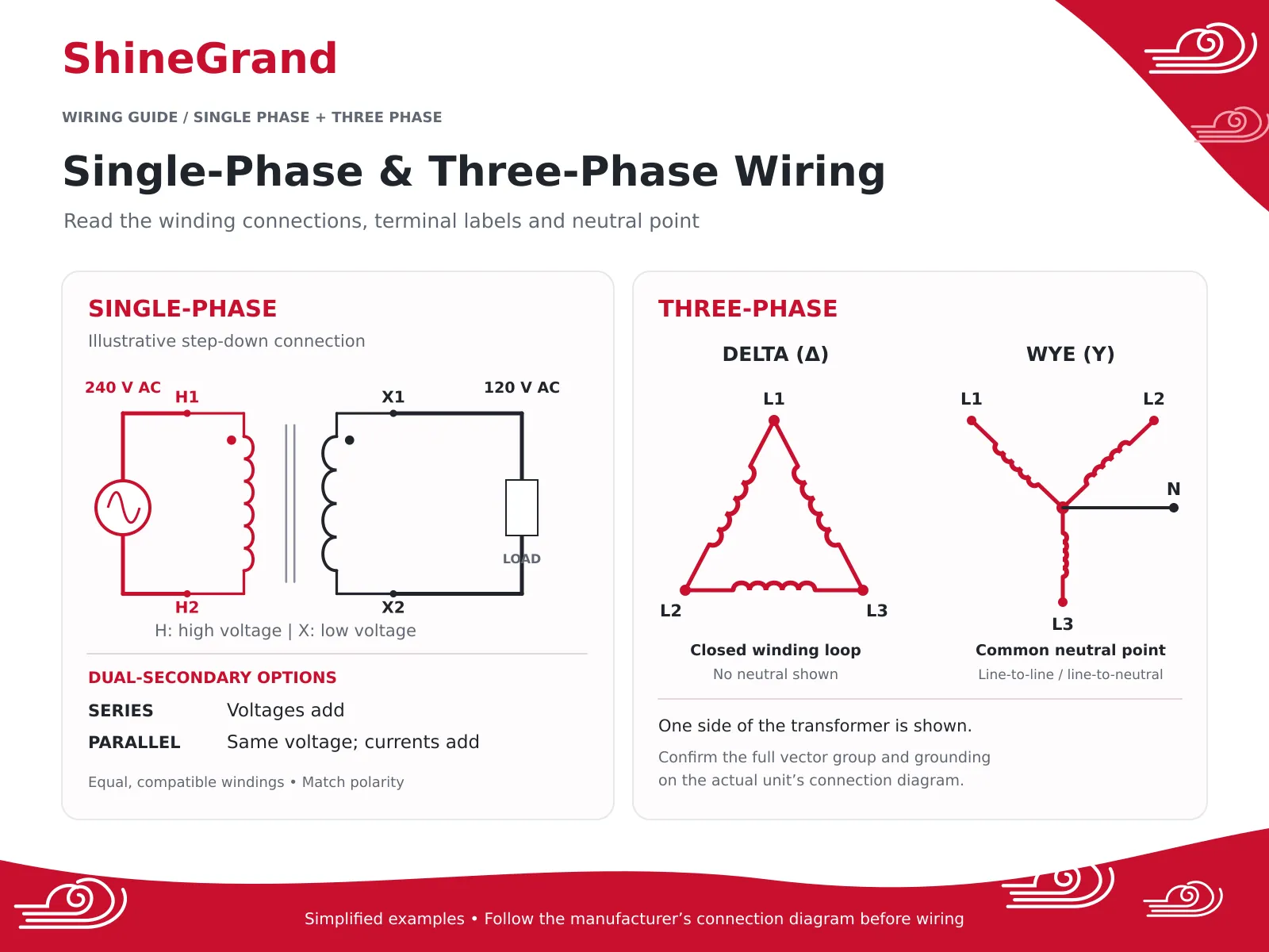
Single-phase wiring is the most common type of wiring which can be found at any place particularly in flat building as well as small machinery. The best example of this wiring is step-down transformer. In the diagram, 240 volts source connects to H terminals of the transformer and 120 volts load connects to the X terminals of the transformer.
Various single-phase transformers can also be categorized as dual voltage transformers because the secondary of these transformers possesses 2 types of winding which may be connected in 2 different ways. When connecting the 2 secondary windings in series the voltages of these winding are added and higher output voltage is provided. In case of connecting these windings in parallel mode, the voltage is kept low but the current increases 2 times. The importance of making a right choice between series and parallel wiring can be seen in various diagrams.
Three-Phase Transformer Wiring: Delta and Wye
Powering most of industrial and commercial appliances are three-phase systems, whose diagrams present two important methods of connection: delta and wye. Being acquainted with both of these systems is paramount in making out a three-phase transformer wiring diagram.
In a wye connection (also referred to as a star connection and shown by the letter Y), one terminal of each of the three coils connects with the neutral point. Such an arrangement allows for obtaining two possibilities of voltage: line-to-line voltage between any two phases as well as lower line-to-neutral voltage. It is because of this versatility that wye is widely used in the buildings where three-phase machines is exploited alongside with single-phase loads.
Unlike wye connections, delta connection (represented by a triangle) constitutes a cycle of three coils. Delta connection is a strong one. Whereas in an open-delta connection if one of the three coils has become inadequate to function, the two remaining can still provide power of three-phase nature, which is close to 58 percent of the initial power.
Polarity: Additive vs Subtractive
Polarity is a concept that confuses the majority of people, but the diagram helps them understand that. The polarity of a transformer can be either additive or subtractive, which depends on winding directions and is reflected in H instances and X instances and the polarity dots. It becomes important in two situations. It is when connecting transformers in parallel that polarity mismatch causes a severe short circuit right after the bank is energized. And it is when two winding circuits are installed that the polarity shows whether the two windings will cancel or add up. Thus, it is necessary to check the dots and the number of terminals before making a connection.
Safety First: Read the Diagram, Then De-Energize
No transformer wiring diagram discussion is complete without the safety rule that comes before any connection. Turn off the supply, and make sure to lock it out before you start working with the terminals at the circuit. Confirm that the circuit is dead by using a multimeter and not just relying on the position of the switch, then confirm that the grounding is good before following the diagram for connections. The diagram gives you a blueprint, but the lockout is what protects you when you are making them work. Working on transformers means working with really high dangerous voltages, so if you are not sure about something, the electrical work should be done by a licensed electrician.
Taps, Grounding, and the Nameplate
Two features on a transformer wiring diagram deserve special attention because they cause a lot of field questions. Firstly, there are tap settings. Many transformers have taps on the primary that allow you to adjust the turns ratio slightly (by a few percent) so that they can deal with persistently high or low supply voltage. The diagram and nameplate display which taps are available and thus which links should be moved so that the output is a desired level. Secondly, there is the grounding aspect. The diagram shows where the system is grounded, which usually takes place at wye neutral. The proper grounding is a requirement for safety and also makes sure that various protection devices operate normally. Always read the nameplate and compare it with the diagram: the nameplate contains information about voltages, kVA rating, vector group or connection scheme helping you understand what a general symbol means in terms of that specific transformer.
Common Transformer Wiring Mistakes to Avoid
Most wiring problems trace back to a small number of avoidable errors, and knowing them makes any transformer wiring diagram easier to follow correctly. If the primary and secondary are mistaken for each other, leading to the connection of the supply to the X terminals instead of the H terminals, the result is a step-up system instead of a step-down one and it can be dangerous. Not taking care of the polarity while connecting multiple systems or wiring up a dual voltage secondary causes a short circuit. Connecting a transformer with a delta or wye configuration that is incompatible with the system it serves results in incorrect voltages or unbalanced working. Not making the grounding connection removes the important safety route. More and more systems are energized before the technician checks them out with a tester.
From Diagram to Real Distribution Equipment
The symbols on a page ultimately represent real hardware in the field. The same H and X markings, delta and wye connections, and polarity rules apply whether you are wiring a small control transformer or a utility-scale distribution unit. ShineGrand Electric manufactures the power and distribution transformers these diagrams describe, including the 6-10KV Oil-Immersed Distribution Transformer for medium-voltage networks, the high-voltage 110-132kV Oil-Immersed Distribution Transformer, the ground-level Three Phase Pad Mounted Transformer Series, and the indoor 20-35kV Epoxy Dry-Type Transformer. Each ships with its own nameplate and connection diagram so the delta or wye configuration, vector group, and terminal markings are clear before installation.
Frequently Asked Questions
How is a transformer wired?
When wiring a transformer, it is necessary to link the incoming system with the part that is known as the primary and the outgoing system is connected with the secondary side of transformer based on wiring schematic and details of nameplate of transformer. One must connect the wires based on number of phases in the transformer and the quantity of voltage necessary. After finishing the wiring connections, it is essential to check the
How do you read a transformer wiring diagram?
First, you should identify the main (H) and minor (X) terminals, which includes looking at the voltages and types of connections (delta or doelta) that appear on the plate. Learn about polarity from the numbers of the terminals and from the dot convention, note whether tbe grounding is applied and check if there are dual voltage or tapping options. The transformer wiring diagram combined with the nameplate tells you exactly how to connect the unit.
How is a 3-phase transformer wired?
Either delta or wye (star) connections may be wired to a three-phase transformer on both sides. The wye connection connects one terminal of all the windings together at a common neutral point and offers line-to-line as well as line-to-neutral voltages. Delta, meanwhile, produces a closed triangular connection with no neutral point. The vector group code on the diagram (e.g. Dyn11) gives all the information about primary and secondary connections and phase differences.
How do you wire a transformer backwards?
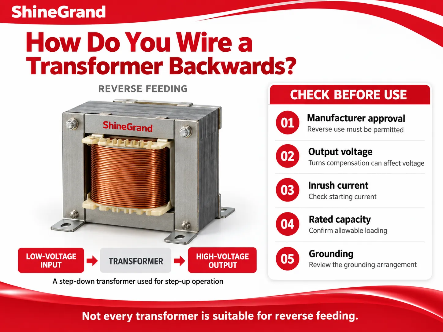
Using a transformer in reverse engineering means working with a step-down transformer like a step-up transformer by feeding the current to the secondary side of the transformer and getting the output from the primary side instead. Many distribution transformers can be used in this manner, but there are some important warnings. Some transformers have a small compensation for turns, which will cause the output voltage when reversed to be not exactly correct and it will be important to check the inrush, capacity, and grounding conditions also. Always ensure that the manufacturer allows use of the reverse wiring method for a particular transformer model.
References
- IEC 60076 — Power Transformers. The international standard series covering transformer construction, vector groups, and connections.
- IEEE C57.12.70 — Terminal Markings and Connections for Distribution and Power Transformers. The standard defining H and X terminal markings and connection diagrams.
- NFPA 70E — Standard for Electrical Safety in the Workplace. Reference for lockout-tagout and safe work practices around energized equipment.
- Electrical Engineering Portal. Neutral educational resource on transformer connections, polarity, and wiring.
- Transformer — Wikipedia. General reference on transformer windings, the dot convention, and delta and wye connections.
Reliable Transformers From ShineGrand Electric
Reading a diagram correctly is the first step; the equipment behind it has to be dependable too. ShineGrand Electric Co., Ltd. designs and manufactures a complete range of power and distribution transformers, in both oil-immersed and dry-type designs, along with high-voltage fuses, surge arresters, and disconnect switches. Every unit comes with clear terminal markings and connection documentation to make wiring straightforward and safe. Whether you are building a new installation or upgrading an existing one, explore our full transformer product range or contact the ShineGrand team for expert guidance tailored to your project.