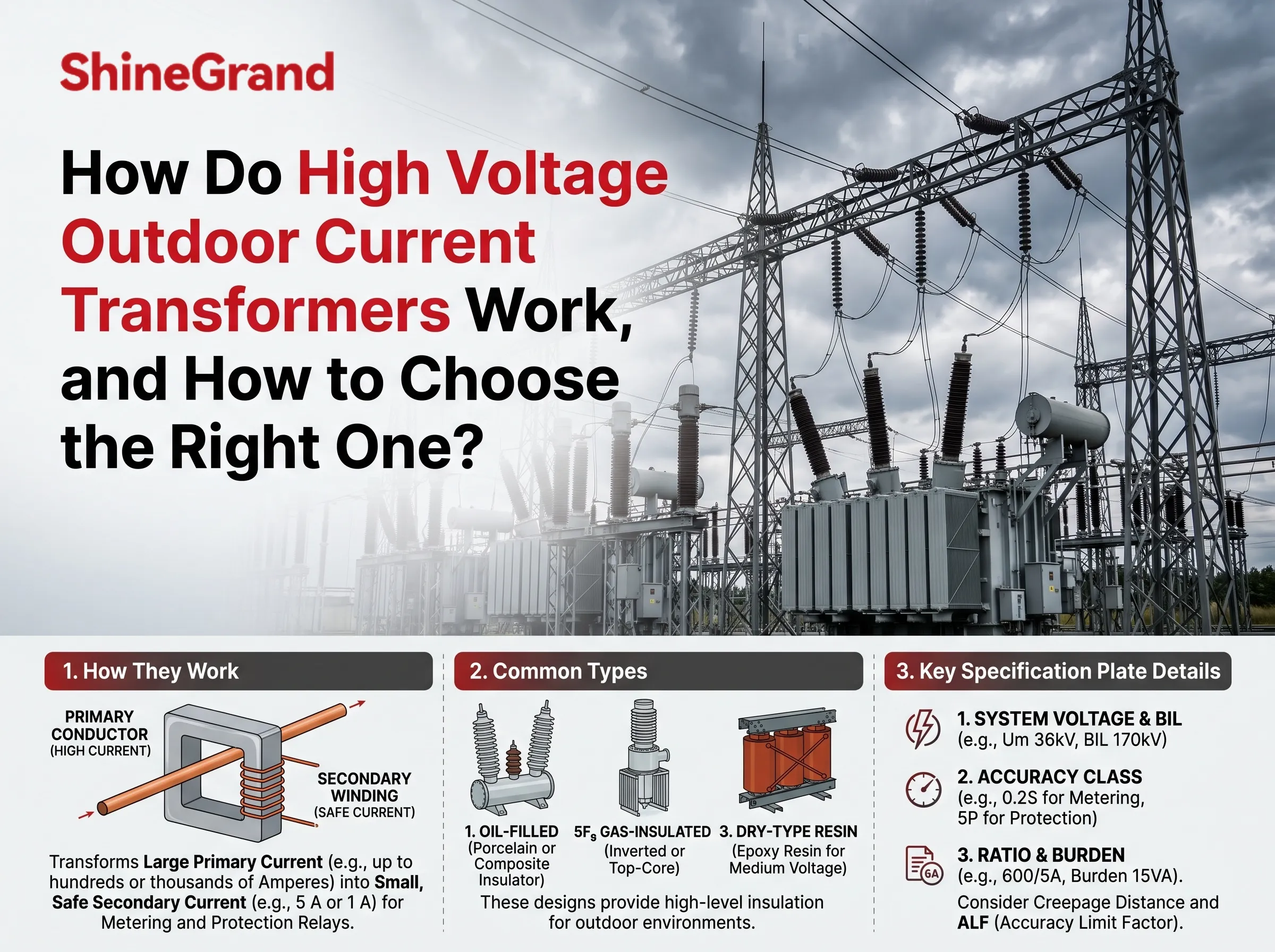
Using a high voltage outdoor current transformer, one can track what occurs on a live 11 kV or 33 kV or even 132 kV line without requiring the meter or relay to be directly connected to it. It transforms the huge primary current (hundreds or thousands of amperes) into a smaller and comparatively safer current (usually 5 A or 1 A) that can be monitored by metering as well as protection devices. Every power station, every major solar and wind connection and every industrial connection of medium or high voltage relies on it. The guide will help to understand the principles of operation behind high voltage outdoor current transformers, what is meant by the ratio and accuracy class of the transformer as described in the specification plate, what types of outdoor current transformers exist, and how to choose a proper outdoor current transformer.
What exactly is a high voltage outdoor current transformer? A high voltage outdoor current transformer (CT) is defined as the instrument transformer that is used in the preventive connection of overhead installations. The CT tag usually delivers small secondary current in the region of 5 A or 1 A. CT’s primary is connected to the overhead line and it provides the electrical isolation of the measuring devices. For instance, a CT with the ratio of 600/5 A will generate 5 A of the secondary current in case there is 600 A of the primary current is available. CT’s outdoor devices have all sorts of protections against the weather conditions (oil-paper insulation, SF6, UV epoxy protecting insulation).
What Is a High Voltage Outdoor Current Transformer?
Meters and relays are delicate, low-voltage devices. A protection relay cannot be wired straight onto a 33 kV conductor carrying 800 A, and nobody would want to work on that panel if it could. A current transformer solves both problems at once. It scales the current down to a standard value the equipment is designed for, and it isolates the low-voltage measuring circuit from the high voltage line.
Outdoor CTs do this job in open-air switchyards, at pole-mounted metering points and at the high voltage connections of generation plants. Indoor CTs do the same job inside metal-clad switchgear. The electrical principle is identical; what changes is how the device is insulated and protected from the environment.
How a current transformer works
A CT consists of a magnetic core and a primary coil and a secondary coil, both of which are wound around the core.
The primary coil is in series with the line conductor, so the full line current passes through it. In such CTs, the primary coil can be a straight conductor or a bar along which the flux flows.
The secondary coil consists of a number of turns of thin copper wire wound around the core. The secondary coil is connected to the meters and the relays.
A current passing through the primary produces flux in the core, and this flux causes the secondary circuit to carry a current. The two currents are proportional to the ratio of the number of turns.
It is important to note that the secondary of a connected CT must never be left open. The absence of current on the secondary side means that the primary current will result in large saturation of the core, and very high voltage can be generated on the secondary, which poses a danger to people and insulation.
A CT is not a power transformer
- Since both types of equipment are called transformers, the concept of current transformers versus power transformers arises frequently. Both transform the same electromagnetic principles; however, the two types perform different functions.Power transformer reduces the voltage in the grid, for instance from 33 kV to 11 kV, transmits real power (endo-adsorption) sometimes up to several MVA.
Contrary is current transformer which does not change the voltage in the network and does not transmit load; it only reproduces a small current which is a copy of the line current for measurement purpose (a few to several tens of VA).
The principal of operation of power transformer is parallel to the line (connected to the same network) and with current transformer the principal is in series with the line.
The efficiency of power transformer is calculated mainly by finding out the ratio of the input to the output power, while the efficiency of current transformer is calculated on the basis of the degree of the compliance of the output current with the input one in different circumstances including during faults.The close relative of these devices is voltage (potential) transformer which performs the same functions for voltage as current transformer does for current; together the devices are known as instrument transformers.
Metering CTs vs protection CTs
CTs function for two distinct purposes. An external CT can have separate cores for each:
Metering cores produce revenue meters, SCADA, and power quality analyzers. They need to be very precise at normal loads, as even minor errors will cause large billing discrepancies. They are intentionally made to saturate during fault conditions to protect meters against high currents.
Protection cores communicate their information to overcurrent, distance, and differential relays. They don’t have to be as accurate at normal conditions, but they still have to be reasonably precise working at very high currents when faults happen to ensure that the relay sees an actual fault current and behaves properly.
Moreover, a standard high voltage outdoor CT can have three or four cores of that kind: one 0.2S metering core as well as two or three 5P20 protection cores.
Outdoor CT vs indoor CT
CTs that are found both indoors and outdoors should not be confused as serving the same purpose. Also, there exist major differences between the two:
Environment – outdoor CTs have to deal with hazardous rains, UV radiation, temperature differences, ice, wind pressure, salt fog, and pollution from industrial sectors. Whereas indoor CTs are working in a clean dry switchgear compartment.
Insulation – outdoor CTs utilize oil-paper insulation and porcupine or polymer housing. On the contrary, indoor CTs are designed by standard insulation resin.
Creepage distance – outdoor CTs have shed profiles calculated according to specific degree of pollution (given in mm/kV).
Mounting – outdoor CTs are free-standing on metal constructions; indoor CTs are getting built in into the switch gear.
Voltage level – indoor CTs work with voltage of up to 35–40.5 kV, while at higher values outdoor CT placements can be found.
Understanding CT Ratios: 200/5A, 400/5A and 600/5A
The ratio is the initial measurement shown on any CT nameplate. This indicates how many primary amperes correspond to the secondary current. For instance,
A 200/5 A CT has a ratio of 40:1. The primary current is 200 A and the secondary current is 5 A; at 100 A in primary it is been 2.5 A in secondary.
A 400/5 A CT has a ratio of 80:1. The primary current is 400 A and the secondary current is 5 A; at 200 A in primary it is 2.5 A in secondary
A 600/5 A CT has a ratio of 120:1. The primary current is 600 A and the secondary current is 5 A; at 300 A in primary it is 2.5 A in secondary.
This is a linear relationship in the normal operating range, which makes CT useful. The reading in the meter or relay is just multiplied by the ratio to obtain the line current.
The selection of current transformer ratio should always balance between the two needs:
For the correct metering, the load current should remain within the range in which the CT device is working at the best performance. If the CT device has a primary rating much higher than the actual load level, in normal operation it will operate at a very low percent of the primary rating which does not guarantee required accuracy level. This provides explanation for existence of extended range classes like 0.2S and 0.5S.
For protection requires higher ratio so that the maximum fault current does not lead the CT into the saturation zone. 20 kA fault is 100 times more than the rating of 200/5 CT and only around 33 times bigger than the rating of 600/5 CT device.
Multi-ratio CT devices with tapped secondaries offerings like 600/5 down to 100/5 gives advantages when there is uncertainty associated with future load. In case of outdoor high voltage CTs it is also probable to replace 5 A with 1 A as secondary current. 1 A means significant reduction of energy lost in the leads which is crucial under circumstances of long cable run from the switchyard to the control house.
Metering Accuracy vs Protection Accuracy: 0.2S, 0.5S, 5P and 10P
The accuracy class of a current transformer indicates the level of inaccuracies allowed and in which situations this transformer can be used. The current transformer classes used in large high voltage outdoor applications that fall under the IEC 61869-2 are as follows:
0.2S: Revenue metering class with a limit of 0.2%, accuracy confirmed down to a current of 1% rated current
0.5S: A class with a limit of 0.5% and extended low current range.
0.2 and 0.5 are traditional classes without the “S.” Here, accuracy applies only to the currents that are 5% of the rated current and above.
5P: The protection class with an error of not more than 5% for the rated current.
10P: The protection class with a maximum error of 10% that fits many of the overcurrent applications.
The protection classes are always indicated together with the accuracy limit factor (ALF). For instance, the 5P20 class means that the accuracy is within 5% up to 20 times the rated current (600 A on a CT of rated 5 A). There are also special classes developed for demanding schemes such as busbar and transformer differential protection – PX, TPX, TPY and TPZ. The distinguishing feature of these classes is that they use knee point voltage and winding resistance to calculate the output.
In North America, the IEEE C57.13 standard is used. The metering classes of the current transformer include 0.15, 0.3, 0.6 and 1.2, while the relaying classes are indicated by C or T and followed by a voltage, such as C400 or C800. Thus, when the current transformer is labeled C400, it means that the transformer can provide 20 times rated secondary current (100 A at 5 A CT) under standard loading conditions while keeping the voltage at 400 and the error value at 10%. If your project uses both IEEE and IEC equipment, make sure to indicate the class according to both standards.
How Burden and CT Saturation Affect Protection Performance
This marks the commencement of many issues regarding CT, constituting the difference between a protection scheme that will work when it is required and one that will not.
What burden stands for is the entire load of the CT secondary, meaning that is consists of the relay or meter input, the cable leads that provide the link with the panel, and all terminal connections. Depending on the chosen measuring system it may be expressed in volt-amperes (VA) according to IEC requirements or in ohms (Ω) according to IEEE. Every CT core has its rated burden, e.g. 15 or 30 VA, and its accuracy class can only be guaranteed up up to this burden.
Saturation takes place because the core is unable to magnetize more units of magnetic flux. For the current to go through the load the CT must create voltages and it goes without saying that to create voltage the core must be magnetized. If the fault current is very high or the burden is too high, the required amount of the flux will exceed the amount that can be magnetized by the core. As a result, the secondary current will die out or become distorted, despite the fact that the primary current is still flowing.
There are serious effects for protection:
The overcurrent relay may detect the lower amount of current than there might be actually in practice. As a result, the relay may operate quite late or not operate at all.
Distance relays might underreach and fail to identify the faults within the prescribed zone.
Differential relays might detect the difference between CTs having different saturation levels, thus resulting in tripping.
Fault currents make it even worse due to the fact that currents usually contain the DC offset. The offset is especially present near the large generators and transformers with high X/R ratio. This would mean that with the offset present the core would saturate much faster, being saturated much sooner than the fault occurs. Previous magnetic transient has worsen the situation as well.
Some practical solutions are given below:
The first one may be about lowering the burden by means of shorter or heavier secondary cables or modern numerical relays characterized by lower input burden.
Another option would be to utilize 1 A rather than 5 A secondaries in case of long runs.
Choosing higher CT could also help to decrease the burden of the fault current compared to the ratings.
Specifying higher accuracy limit factor would also be beneficial in this issue.
As well as using transient-rated classes (TPY, TPZ) or gapped cores when DC offset and remanence factor are taken into account.
Outdoor Current Transformer Types
The main types of outdoor current transformers vary mainly in their method of insulating the high-voltage primary winding from the grounded secondary cores. Each design has a particular voltage rating and intrinsic benefits.
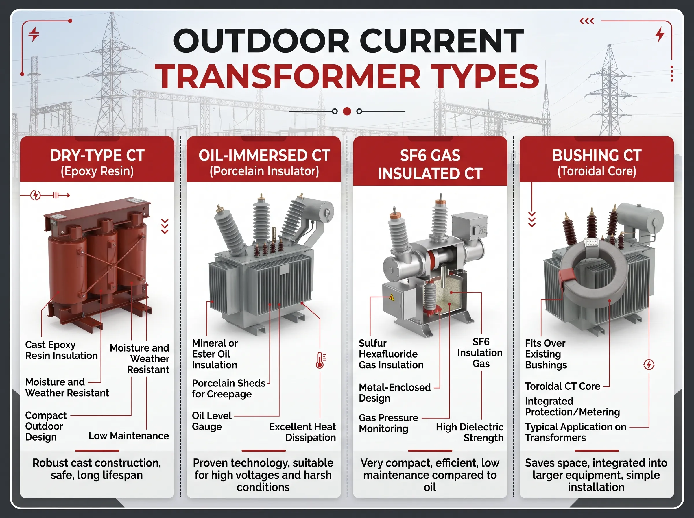
Dry-type outdoor CTs
Dry-type outdoor CTs encapsulate the windings and core within a solid insulating medium resistant to UV and weathering, usually cycloaliphatic epoxy resin or butyl rubber. They are maintenance-free, oil-free, and suited for medium voltage systems anywhere between 5 kV up to about 69 kV. These are commonly found in distribution substations, pole-mounted metering points, and renewable energy collector systems.
Oil-immersed current transformers
Current transformers that are filled with oil utilize oil-impregnated paper insulation within a casing that is made from porcelain or composite material. They are used in most high voltage substations where voltages are applied from 36 kV until extra high voltage. There are two types of configurations:
The first configuration is known as dead tank configuration where the core is placed inside a tank that is grounded at the bottom where the primary conductor passes through the insulator in a U shape. The advantage of this configuration lies in that the center of gravity of the current transformer is located low, thus enabling it to withstand earthquake activity.
The second configuration is called live-tank configuration, where the core is located in the top tank connected to line potential, and then going down to the ground through insulated conductors. The main advantage of this configuration lies in its short primary conductor and effective short circuit operation.
Modern oil-immersed CTs are hermetically sealed with expansion bellows or a gas cushion, so the oil does not contact the air and absorb moisture.
SF6 gas insulated current transformers
The SF6 gas insulated current transformer uses compressed sulfur hexafluoride gas instead of oil and paper. Its design is usually inverted and top-core with composite insulation. One of the main advantages is the absence of oil fire danger as well as less risk for explosion failure and possibility for insulation condition check through gas pressure and density monitoring. The weak point is the maintenance and environment issues with SF6 as one of the strongest greenhouse gases. SF6 CTs are used for voltages from 72.5 kV and up.
Bushing and other special designs
Not all outdoor CTs are built independently. Bushing CTs are toroidal cores placed around the bushing of electrical transformers and dead-tank circuit breakers and the highest number of CTs in a system. The combined instrument transformer combines CT and voltage transformer in one enclosure which helps saving space and foundations at the points of measurement. Sensors based on optics and electronics are used as per IEC 61869 in modern digital substations, while traditional CTs are still in use.
High Voltage Current Transformers by Voltage Level
The design of an insulating material for a high-voltage current transformer depends on the system voltage and the insulation this current transformer would have to withstand. Typical ratings are given below; however, you should verify the use of these ratings with your utility or standard:
For an 11 kV system (Um= 12 kV) the BIL is usually 75kV; dry-type outdoor current transformers and switchgear-mounted ones are used.
For a 22 kV system (Um= 24 kV) the BIL is usually 125 kV; the use of dry-type outdoor and switchgear current transformers is common.
For a 33 kV system (Um= 36 kV) the BIL is usually 170 kV as per IEC, while it could be 200 kV in stringing cases according to IEEE; the use of dry-type outdoor and oil immersed current transformers is accepted.
For the voltage of 66-69 kV the BIL is usually around 325-350 kV; the use of dry-type outdoor as well as the oil immersed CTs is accepted.
As for 110-132 kV voltage systems the BIL normally varies from 450 to 650 kV with the requirement of either oil immersed or SF6 current transformers.
As for the systems with 220kV and above; it is expected that both oil immersed (live-tank) and SF6 CTs would be present.
The 33 kV outdoor current transformer should be pointed out as it occupies a unique place where dry-type and oil-immersed designs are used in the competition with each other. In typical 33 kV feeder or renewable plant interconnections buyers would request the maximum system voltage of 36 kV with the withstand voltage of 70 kV, the BIL of 170 kV, the ratios like 200-400/1 A or 400-800/1 A, one 0.2S metering core, two 5P20 protection cores, short-time current of 25 kA during one or three seconds, creepage of 25 or 31 mm/kV depending on the level of pollution on the site of Transformer.
How to Select a High Voltage Outdoor Current Transformer
A CT specification that is well done will take into account the following parameters. Failure to include any of the following is the most common reason for the inability to compare quotations from different manufacturers.
1.System data – system nominal voltage, system maximum voltage, frequency and earthing.
2.Insulation level – BIL, withstand level and switching impulse voltage from 300 kV and above.
3.Primary rating – maximum primary current, information about multiple ratios and reconnections and continuous thermal current/rating factor in case of overloads.
4.Secondary rating – either 1 A or 5 A based on the length of the cable and the type of relay used.
5.Cores – number of cores and primary defined values for every core such as ratio, accuracy class (e.g. 0.2S, 5P20, PX, C400) and burden value.
6.Short circuit rating – overload thermal current and its duration (e.g. 31.5 kA for 1 s), and overload dynamic current value (typically 2.5 times).
7.Environment – pollution class and creepage distance, altitude, range of temperature, seismic requirement and wind and ice loads.
8.Construction – dry type, oil-insulated or SF6; porcelain or composite insulator; and installation type.
9.Standard – IEC 61869-1 and IEC 61869-2 or IEEE C57.13 standards and utility-specific requirements.
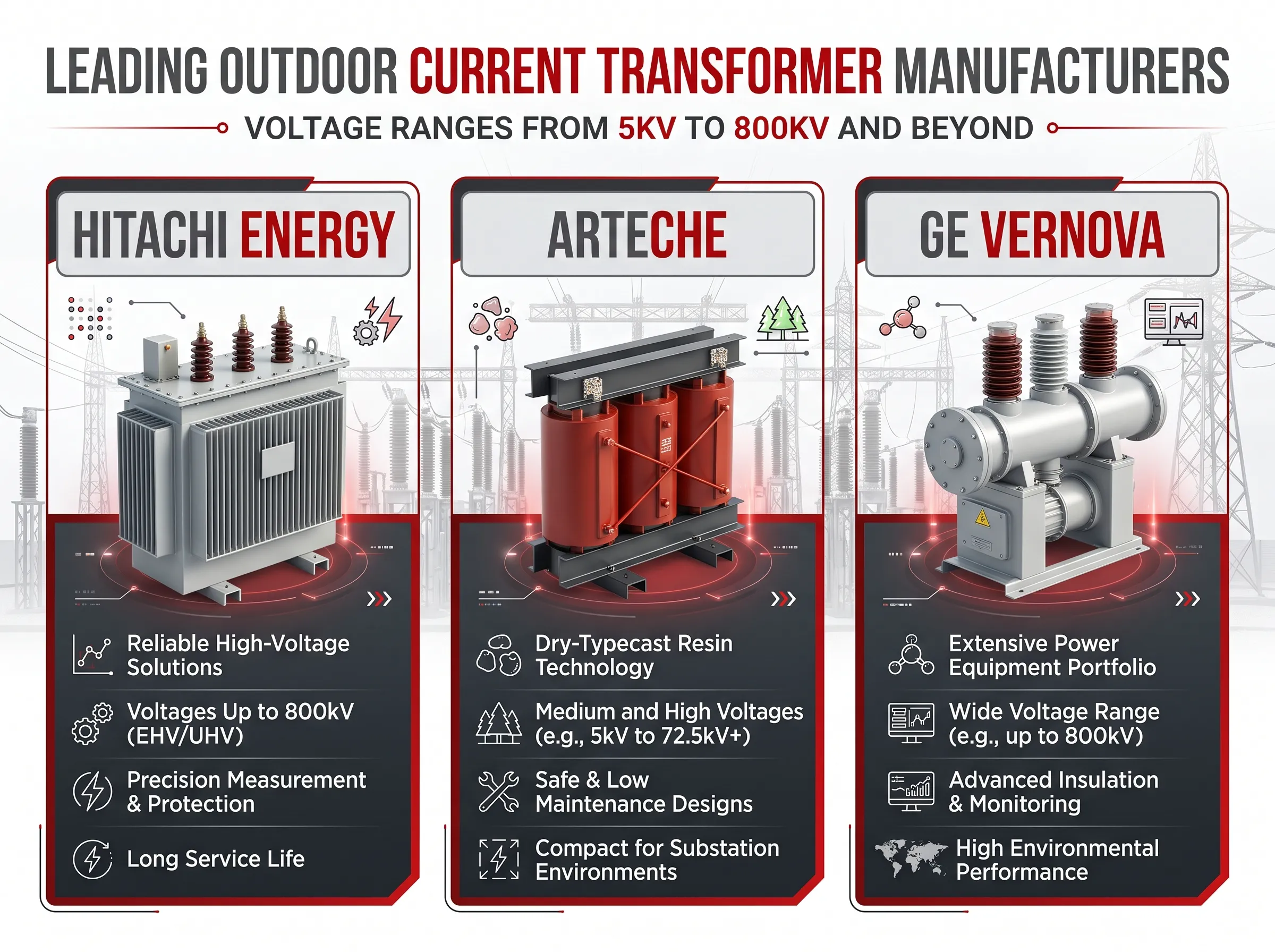
Leading Outdoor Current Transformer Manufacturers
Searches for outdoor current transformer manufacturers usually lead to a handful of global names. Their product pages and brochures are excellent technical references for anyone writing a specification.
- Hitachi Energy COF is an oil-paper insulated, top-core outdoor CT for 25 to 170 kV, hermetically sealed, with porcelain insulators as standard and silicone rubber as an option. Hitachi Energy also offers the TG series, SF6 gas-insulated CTs for 72.5 to 800 kV, and further ranges such as the CA series.
- Arteche offers the CR, CP and CE series of dry-type outdoor CTs for about 5 to 69 kV, with epoxy resin insulation, including cycloaliphatic epoxy versions for harsh UV and pollution environments. These are a useful reference for medium voltage outdoor resin CTs.
- GE Vernova offers the OSKF range of oil-insulated CTs for high voltage up to 800 kV, and the SUPERBUTE family of outdoor CTs molded from butyl rubber, such as the JKW-350ER 69 kV, 350 kV BIL unit, with wound-primary and bar-primary versions depending on ratio.
Comparing these product lines is a good way to understand the market. Dry-type resin and butyl designs cover medium voltage up to about 69 kV, oil-paper designs cover the broad middle of high voltage transmission, and SF6 designs take over at the highest voltages.
Common Mistakes When Specifying Outdoor CTs
- Determining the turn ratio based on the operational load, then ensuring that the protection core can handle the fault level.
Using a rated burden far greater than necessary “just in case”, resulting in an oversized and costly core that does not provide any additional benefits.
Adopting a regular 0.2 or 0.5 class for revenue metering while the actual loading is very low instead of a 0.2S or 0.5S class.
Using the same specifications for indoor CT for outdoor CT disregarding the creepage, UV exposure and temperature considerations.
Using IEC and IEEE accuracy classes in the same setup without ensuring that the relays and CTs are compatible.
Keeping an extra secondary core open instead of shorted and grounded.
Where ShineGrand Fits In
ShineGrand Electric does not manufacture current transformers. For CTs, the manufacturers above and specialist instrument transformer suppliers are the right sources. CTs are, however, installed in the same substations and at the same connection points as the equipment ShineGrand does build. If you are planning a distribution substation or a renewable energy collector system, ShineGrand supplies distribution and power transformers, including 110–132 kV oil-immersed transformers, together with surge arresters, fuse cutouts and disconnect switches for the rest of the outdoor protection package.
Frequently Asked Questions
What is a high voltage outdoor current transformer used for?
It measures the amount of electricity passing through a high-voltage line and converts it to a low current (usually five amperes or one ampere) for billing meters, monitoring systems, and protective relays. It prevents the low-voltage device from being affected by the high-voltage system. Versions designed for outdoor use are designed for open-air substations and transmission lines.
What does a 600/5 A CT mean?
It means the CT produces 5 A on its secondary when 600 A flows through its primary, a ratio of 120:1. The relationship is proportional, so 300 A in the primary gives 2.5 A in the secondary. Meters and relays multiply the secondary reading by 120 to display the actual line current.
What is the difference between a current transformer and a power transformer?
A power transformer changes the voltage of the grid and delivers power to loads. A current transformer does neither. It is an instrument transformer that produces an accurate, scaled-down copy of the line current for measurement and protection, and it is connected in series with the line rather than across it.
What is the difference between 0.2S and 5P20?
The class of meter accuracy is 0.2S which shows that the error ratio does not exceed ± 0.2% in the rated currents with its precision guaranteed down to 1% of the rated current. The class of protection is 5P20 meaning that the total error remains within 5% up to 20 times higher values than the rated current for specified burden. So, while the meter core must have the high precision of measurements, the protection core should have the adequate accuracy during very high fault currents.
Should I choose a 1 A or 5 A secondary?
For outdoor power utilities with long cable runs to the control room, choosing 1 A is quite common due to the fact that cable losses are inversely proportional to the square of the current. 5 A is still widely used in America and in cases where older meters and relays are designed to work with 5 A.
What happens if a CT secondary is left open?
In the situation where there is current in the primary circuit and an open in the secondary, the core gets saturated and very high voltage can be observed across the terminals of the secondary. This creates a serious risk of a shock and can lead to insulation breakdown of the CT. It is important to short the secondary using shorting links before a meter or relay is disconnected and to short any unused core after proper grounding.
What causes CT saturation?
Saturation happens when the core of the transformer gets to its maximum magnetic flux density. The common reasons for saturation include excessive fault currents that are far greater than the permissible limit of current transformers, too much secondary burden on the transformer, DC offset seen in many fault currents, and remnant magnetism of the transformer core. Saturation can lead to incorrect timing of operation of protection relays, misinterpretation, and insufficient operation.
Oil-immersed, dry-type or SF6: which outdoor CT is best?
There is no best type in the field. Quite often dry-type resin CTs are appropriate for voltages up to 69 kV where they require no maintenance. Oil-immersed CTs are the standard solution to most voltage levels tested over decades. SF6 CTs dominate the field starting from 72.5 kV and above where the avoidance of oil and the requirement for gas monitoring are considered.
References
- IEC 61869-1 and IEC 61869-2 — Instrument transformers: general requirements and additional requirements for current transformers. International standards for CT ratings, accuracy classes and tests.
- IEEE C57.13 — Standard Requirements for Instrument Transformers. North American CT ratings, metering classes and C/T relaying classes.
- IEEE C37.110 — Guide for the Application of Current Transformers Used for Protective Relaying Purposes. CT saturation, burden and transient performance.
- Electrical Engineering Portal (EEP). Technical articles on CT selection, accuracy classes and saturation.
- Wikipedia — Current transformer. General background on CT principles and construction.
Building an Outdoor Substation?
Choosing a high voltage outdoor current transformer comes down to a clear specification: system voltage and insulation level, ratio, accuracy class and burden for every core, short-circuit rating and site conditions. Get those right and both your metering and your protection will do their jobs. For the transformers, surge arresters, fuse cutouts and disconnect switches that complete the outdoor installation, contact ShineGrand to discuss your project.