An unexpected generator disconnection occurred in 2019 at a large Texas Gulf Coast gas burning electric generating facility. The disconnection occurred when a protection relay opened due to a fault in the winding of the generator step up transformer (the equipment that increases the voltage of the generator output from 22 kV to 345 kV). The generator output was 600 megawatts and the disconnection occurred in less than one-tenth of a second. The transformer failed and the facility suffered millions in lost generation and the transformer took 8 months to get repaired because the transformer is not a standard item and is one of a kind, it can weigh more than 300 tons, has a lead time of months or years before it can be delivered.
The story emphasizes that the generator step-up transformer (GSU) is the most vital single component in every power plant. The GSU serves as an interface between the generator and the grid. If there is no GSU between a turbine (gas, steam, nuclear or hydro power) and the transmission network, the energy produced cannot flow into the transmission system. In addition to providing a basic description of the GSU, this article describes its differences from other electric transformers and provides information on the specifications, protection and appropriate maintenance practices for GSU transformers which exist in every power plant.
What Does GSU Stand For?
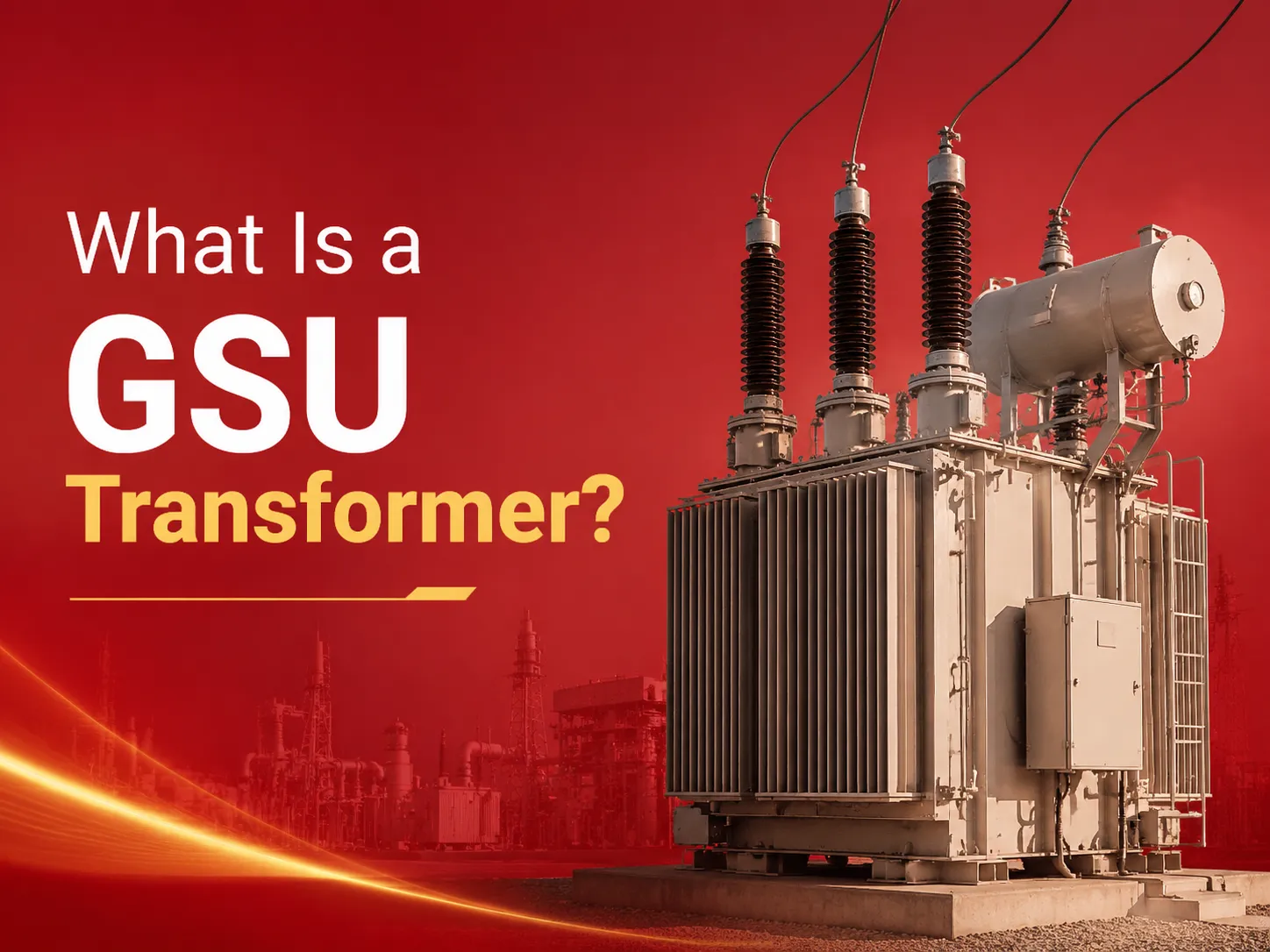
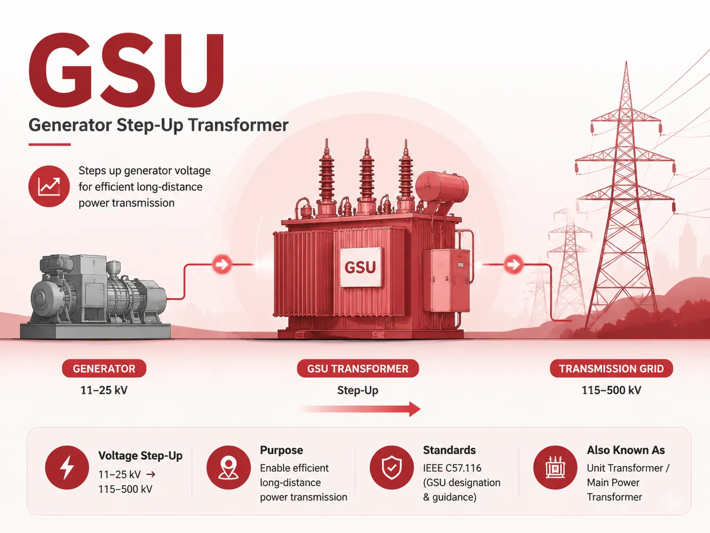
A Generator Step-Up transformer (GSU) is a device used in the field of electrical engineering to connect an electrical generator’s output to the electrical transmission grid. A major function of the GSU is to step up the voltage of the generator’s output (typically 11 kV to 25 kV) to higher voltage levels for transmission (typically 115 kV, 230 kV, 345 kV, or 500 kV) so that electricity can be moved efficiently over long distances. The term “step-up” describes the increase in voltage from the primary (generator) side of the transformer to the secondary (transmission) side.
Many utilities or equipment manufacturers refer to Generator Step-Up (GSU) transformers as “unit transformers” or “main power transformers”. While these terms may be used colloquially in the electric utility industry, the technical definition of GSU transformer is provided by standard documents, such as IEEE C57.116, Generator Step-Up Transformers. These documents stipulate what constitutes a GSU transformer, and therefore distinguish GSU as a separate type of Power Transformer from other Power Transformers located in the Generation Station such as Station Service Transformers and Unit Auxiliary Transformers.
How a GSU Transformer Functions in a Power Plant
A normal thermal or hydroelectric power station produces electricity at a medium voltage level. This is because it would be impractical to generate electrical power directly at the transmission voltage level since very thick insulation on the stator of the generator would be necessary to accommodate the higher voltage, resulting in larger, more expensive generators and considerably greater difficulty in keeping them cool. Instead, the generator is designed to produce output at an optimal voltage level; one where the insulation needed is balanced with the current capability of the generator and the mechanical size of the generator itself. The generator step-up (GSU) transformer then raises the generator’s output to the same voltage as the transmission system.
The configuration of the GSU transformer is quite simple. The low voltage winding of the GSU transformer runs directly to the terminals of the generator using either an isolated phase bus or cable. The high voltage winding connects to the transmission system via a circuit breaker and disconnect switch. Most modern installations use a three-phase GSU transformer with a delta-connected low voltage winding and a wye-connected high voltage winding, where the wye neutral is solidly grounded or grounded through an impedence. The vector group is normally Dyn11 or something similar, with a 30 degree phase shift that provides suppression of third harmonic currents.
The Generator Step-up Transformer (GSU) is continually in operation with the total output of the Generator; therefore, its reliability is critical. A GSU failure will take an entire generating unit off-line. Unlike a Distribution Transformer, which can be bypassed, or a Station Service Transformer, which has a redundant power supply, a GSU has no redundancy and represents a single point failure in a generating plant. As such, GSU transformers are manufactured with more conservative design margins than almost any other type of power transformer.
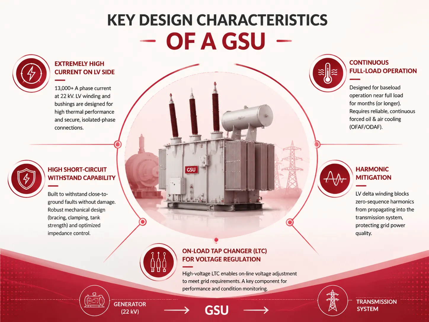
Key Design Characteristics That Distinguish a GSU
A generator transformer is not merely an enlarged distribution transformer; it has many design features that reflect a different kind of operating environment, as follows:
- Extremely high current on the low‑voltage side. The 500 MW generator at 22 kV produces over 13000 A of phase current from an external source. Therefore, both the low voltage winding of the generator step-up transformer (GSU) and the bushings must have sufficient thermal characteristics so as to not overheat when supplying continuous current to the generator from the generator’s terminals. In addition, the isolated-phase bus connections must be designed in such a manner that they properly match the transformer low voltage terminal configuration.
- Continuous full‑load operation. A baseload Generator Step-Up (GSU) can be compared to a transmission and distribution transformer in that it has an operating cycle; however, the GSU is usually subjected to loads for much longer periods of time with the possibility of operating near full load for many months (or longer). The prolonged, continuous, and steady-state thermal stresses on the GSU create an immediate need for a continuous (typically forced oil and air (OFAF or ODAF)) cooling system that operates continuously and without fail.
- High short‑circuit withstand capability. The GSU is designed to withstand a close‑to the “ground” fault on the transmission system with no internal damage. The winding bracing, core clamping, and tank structure have been designed to withstand the HUGE electromagnetic force caused by a fault. The short-circuit impedance prevents excessive fault currents from coming from the grid while also minimizing the voltage drop at normal load.
- Harmonic mitigation. Transformers can be affected by harmonic distortion caused by generators, especially those using inverter-based resources. To stop the harmonics from moving into the transmission system, GSU’s winding arrangement has (common delta configurations at the LV side) been created so that all of the zero sequence harmonics are stopped before it reaches the utility.
- Load tap changer (LTC) for voltage regulation. Most GSU transformers feature an on-load tap changer installed on the high-voltage winding which enables the operator to continuously adjust the transmission voltage to meet grid requirements while keeping the transformer in service. The LTC is one of the high-maintenance components within the transformer and has become an area of focus for condition-based monitoring programs.
GSU vs. Other Power Transformers: Key Differences
The table below clarifies how a GSU transformer compares to other common types of power transformers found in generation and transmission systems.
| Characteristic | GSU Transformer | Transmission Transformer | Distribution Transformer |
|---|---|---|---|
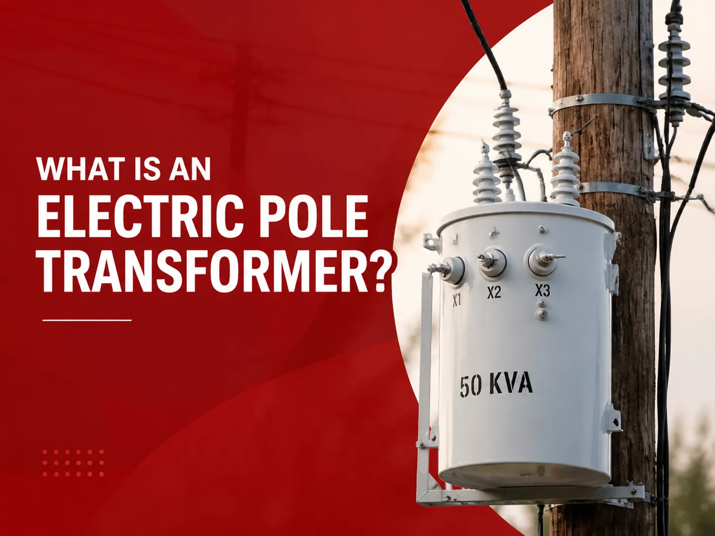
| Location | Power plant, directly connected to generator | Substation, between transmission voltages | Pole or pad, between distribution and utilization |
| Typical voltage range | LV: 11–25 kV; HV: 115–500 kV | HV: 115–765 kV; LV: 34.5–230 kV | HV: 2.4–34.5 kV; LV: 120–600 V |
| Typical MVA rating | 50–1,200 MVA | 50–1,000 MVA | 0.005–5 MVA |
| Load profile | Continuous near full load | Variable; load cycles daily and seasonally | Highly variable; low average utilization |
| LV winding connection | Delta (typical) | Wye or delta | Wye or center‑tapped delta |
| Cooling type | OFAF, ODAF, or ODWF | ONAN, ONAF, or OFAF | ONAN (oil‑filled) or AN (dry‑type) |
| LTC | Almost always present, on HV side | Often present, for voltage regulation | Rare; off‑circuit taps if needed |
Is a GSU the Same as an MPT?
GSU and MPT (Main Power Transformer) are sometimes used interchangeably; however, GSU and MPT have different meanings. The MPT is the transformer that converts electrical energy from the generating units to an alternating current (AC) signal that enters the utility grid; therefore, the MPT in a generating facility is also known as the GSU. In a single generator facility, the GSU is the MPT. In a multi generator facility, there may be both GSU and MPT transformers. Thus, for each of the multi-generator units there may be GSU transformers and one MPT transformer. The GSU provides connection to the unit generator; the MPT may provide additional voltage and connection to either the utility or the regional interconnect. For the majority of single unit installations GSU and MPT refer to the same transformer.
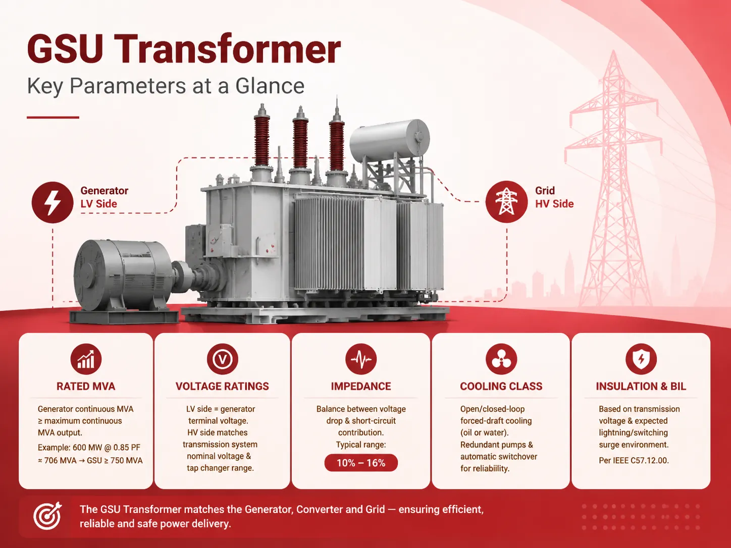
Specifying a GSU Transformer: Key Parameters
The OEM or Developer defines the use of a Generator Step-Up (GSU) transformer, essentially an exercise in matching the Generator, Converter and Grid System, as guidance for design, production and shipping of the GSU Transformer. The following are the key parameters of the GSU Transformer:
- Rated MVA. The generator’s continuous MVA output must be equal to or greater than the maximum continuous MVA output of the generator with consistent overhead operation. For example, a 600 MW generator rated at a 0.85 power factor would produce an output of approximately 706 MVA and should therefore be connected to a generator step up transformer (GSU) that is rated at 750 MVA or higher.
- Voltage ratings. The generator terminal voltage and the low-voltage rating are the same. The transmission system(s) nominal voltages (HV/BT) will also be matched to the appropriate tap changer ranges.
- Impedance. A compromise exists between two competing requirements, the first is to have a small enough short-circuit impedance to reduce voltage drop and reactive power requirements, and the second is to have a large enough impedance such that the short-circuit current contributions to the grid are limited. Typical GSU impedances will range between 10% and 16% based on MVA rating.
- Cooling class. Units that produce a consistent output of power (baseload) commonly utilize an open- or closed-loop forced-draft cooling system. The cooling systems typically include pumps and convection cooling fans for circulating either oil or water through the units for cooling. Most units categorized as critical include redundant pumping systems and automatic switchover from main units to backup systems to ensure redundancy.
- Insulation level and BIL. When choosing the basic impulse insulation level (BIL), different features will be included; however, when establishing the BIL level for an electrical device, the following must be considered: (1) The transmission voltage. (2) The magnitude of the expected lightning/ switching surge environment. The BIL requirements for each of these items are defined by the various voltages as set forth in IEEE C57.12.00.
Installation, Commissioning, and Maintenance Best Practices
The installation of a Generator Step-Up (GSU) transformer requires significant civil and electrical work. The foundation for the transformer must be able to support hundreds of tons of weight and contain oil in a manner that meets environmental regulations. The isolated phase bus must also be installed correctly. After the transformer is installed, a full suite of field tests is conducted before the transformer has been energized: insulation resistance, winding resistance, turns ratio, power factor/dissipation factor and sweep frequency response analysis (SFRA). These tests serve as baseline values for future condition monitoring of the transformer. The on-load tap changer will be exercised throughout its full range.
An annual dissolved gas analysis of the insulating oil, periodic power factor testing, infrared thermography of bushings and connections, and continuous monitoring of winding temperatures and oil levels are included in the condition-based maintenance programme of GSU in service. Many of today’s GSUs have online monitoring systems that give present or ‘real-time’ readings to the plant control room. The aim is to identify developing faults, such as a developing hotspot, partial discharge or failing bushing, at an early time so that an outage can be scheduled rather than reacting to the occurrence of a forced failure. For a deeper understanding of the thermal limits that govern transformer loading and life expectancy, our guide on transformer sizing and the 80% loading rule provides context applicable to all power transformers, including GSUs.
Frequently Asked Questions
What does GSU stand for in electrical?
GSU or Generator Step-Up is an electrical engineering term. A GSU transformer converts a generator’s output voltage and increases it to High Voltage for transmission via Electric Grids.
What is the difference between transformer and GSU?
A GSU is an electric transformer used between a network and a generator. GSUs are distinct from conventional transformers through their high voltages (current) on the low voltage side, their ability to maintain continuous current levels indefinitely, and their winding configurations (wye with delta) and construction including load tap changers (LTCs). While GSUs are transformers, standard power transformers were not designed to handle the particular thermal/electrical conditions associated with the direct connection of generators.
Is a GSU the same as an MPT?
Typically, the Main Power Transformer (MPT) and GSU Transformer are comprised of the same Transformer in a being a single-unit power plant. In a multi-unit generating station with a common switchyard, the MPT may be referring to the Transformer which steps up a common bus from multiple units, whereas the GSU will be the only Transformer directly connected to the specific unit.
What is the meaning of gsu?
GSU Generator Step-Up is abbreviated as GSU; this term refers to a transformer that increases voltages from the generator side (11-25 kV) to the transmission side (typically 115 kV and above). GSU is frequently referenced in the power plant engineering industry, as well as in standards like IEEE C57.116.
References
- IEEE C57.116 — IEEE Guide for Transformers Directly Connected to Generators.
- IEEE C57.12.00 — IEEE Standard for General Requirements for Liquid‑Immersed Distribution, Power, and Regulating Transformers.
- U.S. Department of Energy — Large Power Transformers and the U.S. Electric Grid.
- IEC 60076‑7 — Loading guide for mineral‑oil‑immersed power transformers.
A GSU transformer is a singular piece of equipment with a singular mission: to reliably transfer every megawatt a generator produces into the transmission grid, day after day, year after year. It is designed for the heaviest continuous duty in the power system, and its failure is measured not just in repair costs but in lost generation revenue. Understanding its design, its operation, and its maintenance requirements is essential for anyone responsible for power plant assets. At ShineGrand Electric, we engineer power transformers — including generator step‑up units — with the conservative design margins and the rigorous factory testing that this critical application demands, because a transformer that connects a generator to the grid has no room for compromise.