Every transformer relies on one thing to function as designed: correct, tight, and well‑planned connections. Whether you’re an electrician landing the secondary cables of a pad‑mounted unit, a panel builder wiring a control transformer, or a facility engineer verifying a dry‑type installation, the principles are the same. A wiring error can instantly destroy an expensive transformer, trip upstream protection, or create a shock hazard that remains hidden until someone touches an energized enclosure. According to data from the Electrical Safety Foundation International, wiring faults and loose connections contribute to an estimated 25% of electrical failures in distribution equipment — failures that are overwhelmingly preventable through correct installation and torque verification. This guide walks through the essential steps, from reading the nameplate to tightening the last lug, with the goal of making your next transformer termination both safe and code‑compliant.
Decoding the Nameplate Before a Single Wire Is Landed
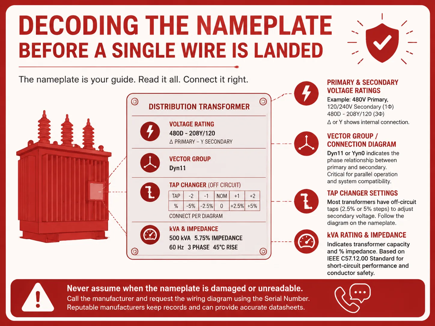
All transformers come with an accompanying nameplate that is used for primary connection purposes. Ensure that you read the entire nameplate before establishing any connections to the transformer. On the nameplate you will find information regarding:
- Primary and secondary voltage ratings. If you have a single-phase transformer, the nameplate would indicate “480V Primary, 120/240V Secondary”, whereas for a three-phase transformer it would read “480D – 208Y/120”. The delta (Δ) or wye (Y) symbol represents how the windings are connected internally.
- Vector group or connection diagram. Dyn11 or Yyn0 are how we refer to the phase relationship of the transformer’s secondary related to the transformer’s primary. This is very important when connecting transformers together to operate in parallel to an existing system that requires a specific phase rotation configuration.
- Tap changer settings. Most distribution transformers contain off circuit taps that adjust secondary voltage using either 2.5 or 5 percent increments. The nameplate diagram depicts the connection method for each tap point.
- kVA rating and impedance. The IEEE C57.12.00 Standard covers things such as Short Circuit Ratings (of transformer design) and expected current carrying capacity of conductor systems due to distribution transformer failures.
Never make any assumptions about an electric motor’s nameplate if it’s been destroyed or is difficult to read; instead, call the manufacturer and request the replacement wiring diagram by providing them with your motor’s Serial Number. If you’re dealing with a reputable manufacturer, they will have a record keeping system in place to access the datasheet.
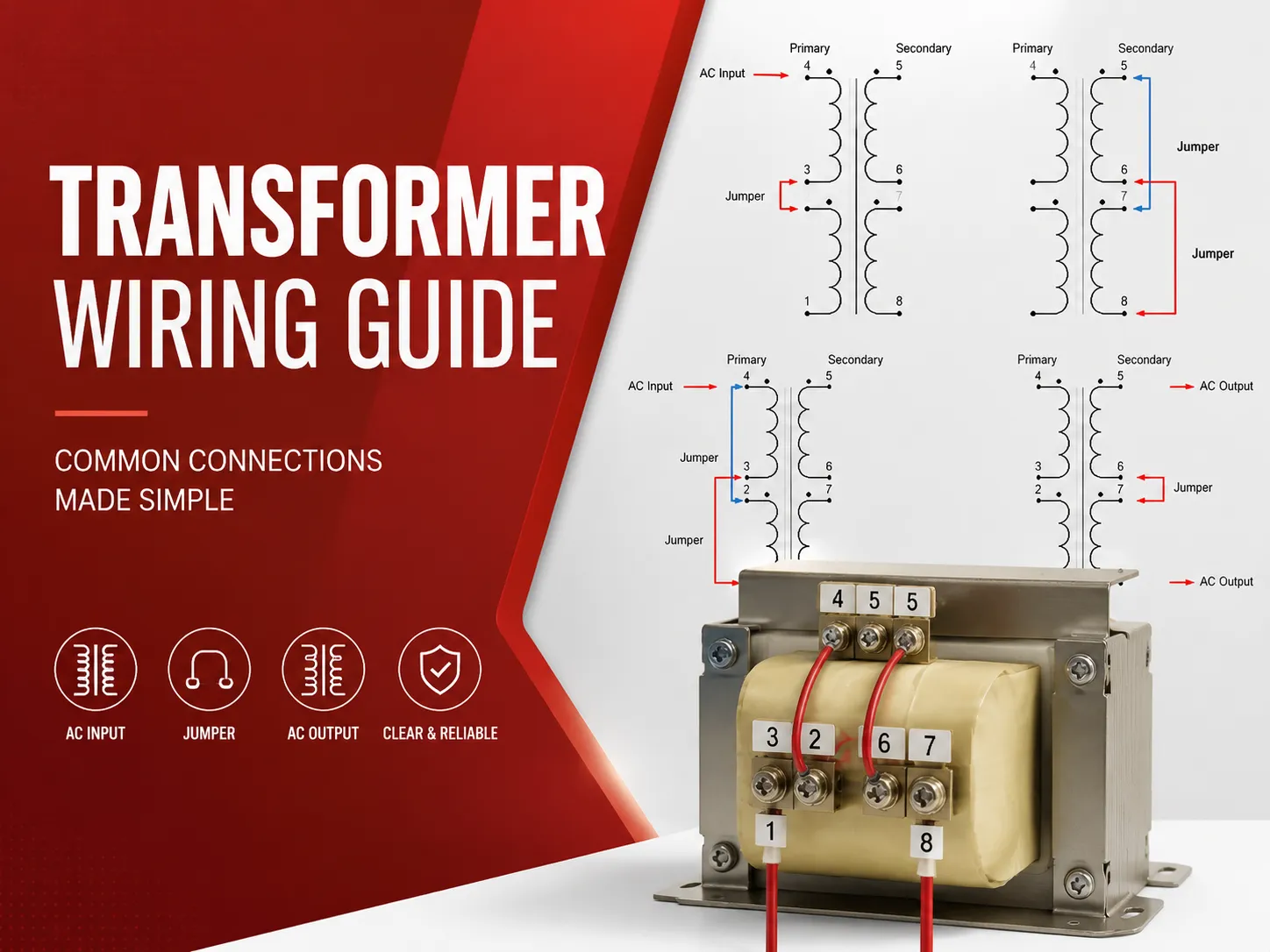
Terminal Markings and Polarity: The Universal Code
The terminal markings of a transformer enable a reader to accurately interpret any wiring diagram after the markings have been learned. For single-phase transformers, the high voltage terminals will be labeled H 1 and H 2; for low voltage terminals the markings will be X 1 and X 2, respectively. The relationship between the H 1 and X 1 terminals determines polarity. If the H 1 terminal is instantaneously positive, the X 1 terminal will also be instantaneous positive. This same relationship between H 1 and X 1 is important in the applicable circuit configurations of transformers, such as when they are banked together in parallel, or for creating a split-phase 120/240 volt service.
For three-phase transformers, the pattern continues H1, H2, H3 on primary; X1, X2, X3 (and optional X0 if neutral is brought out) on secondary. The connection diagram (delta, wye, or zig-zag) tells you what terminals connect together and where to land the incoming and outgoing conductors. The greatest mistake in three-phase installations is reversing one winding, causing a circulating current that could trip protection or overheat transformer with no load connected.
Step-by-Step: Wiring a 480V to 120/240V Single‑Phase Unit
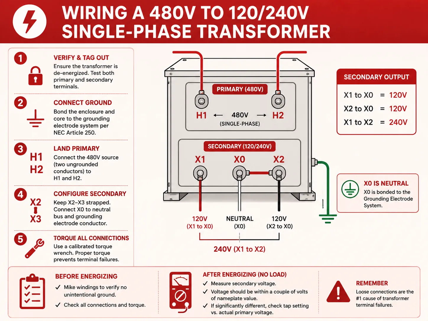
This configuration is typical of light commercial and residential pad mounted service in North America and is a clear illustration of all principles. The primary side of the transformer provides 480 volts from H1 to H2. The secondary side produces a center tapped 120/240v output such that X1 to X0 is 120 volts, X2 to X0 is 120 volts, and X1 to X2 is 240 volts. Terminal X0 is bonded to the Grounding Electrode System and acts as the neutral.
The wiring sequence for a qualified electrician is:
- Verify the transformer is de‑energized and tagged out. Use a rated voltage tester on both primary and secondary terminals.
- Connect the equipment grounding conductor. According to Article 250 of the National Electric Code, the transformer enclosure and core must have a ground connection to the supply-side grounding conductor.
- Land the primary conductors. The 480V power source will typically consist of two ungrounded conductors coming from a 480V panel or disconnect. Connect these two wires to terminals “H1 and H2”. There is no need to worry about phase rotation when connecting a single phase primary.
- Configure the secondary. When the nameplate reads X2 and X3 connected via a strap provided, you will have X0 connected to a grounding electrode conductor and neutral bus connections. You will connect your load conductors of the 120/240 volt circuit to X1 or X2 or X0 depending on their connection requirements.
- Torque every connection. A calibrated torque wrench should always be utilized, using the value given on the nameplate or in the manufacturer’s instructions. As stated in NECA 10 series standards, it is advised that all bolted connections be checked for proper torque because loose bolted connections are the number one cause of transformer terminal failures.
Make sure that the windings were miked before they were put in service in order to verify that there was no unintentional ground (accidental ground). Once power is again supplied, measure secondary voltage with no load present; it should be within a couple of volts of nameplate value. If the measured voltage is significantly different from nameplate value, check your tap setting compared to the actual primary voltage.
Three‑Phase Configurations: Delta, Wye, and Managing Phase Rotation
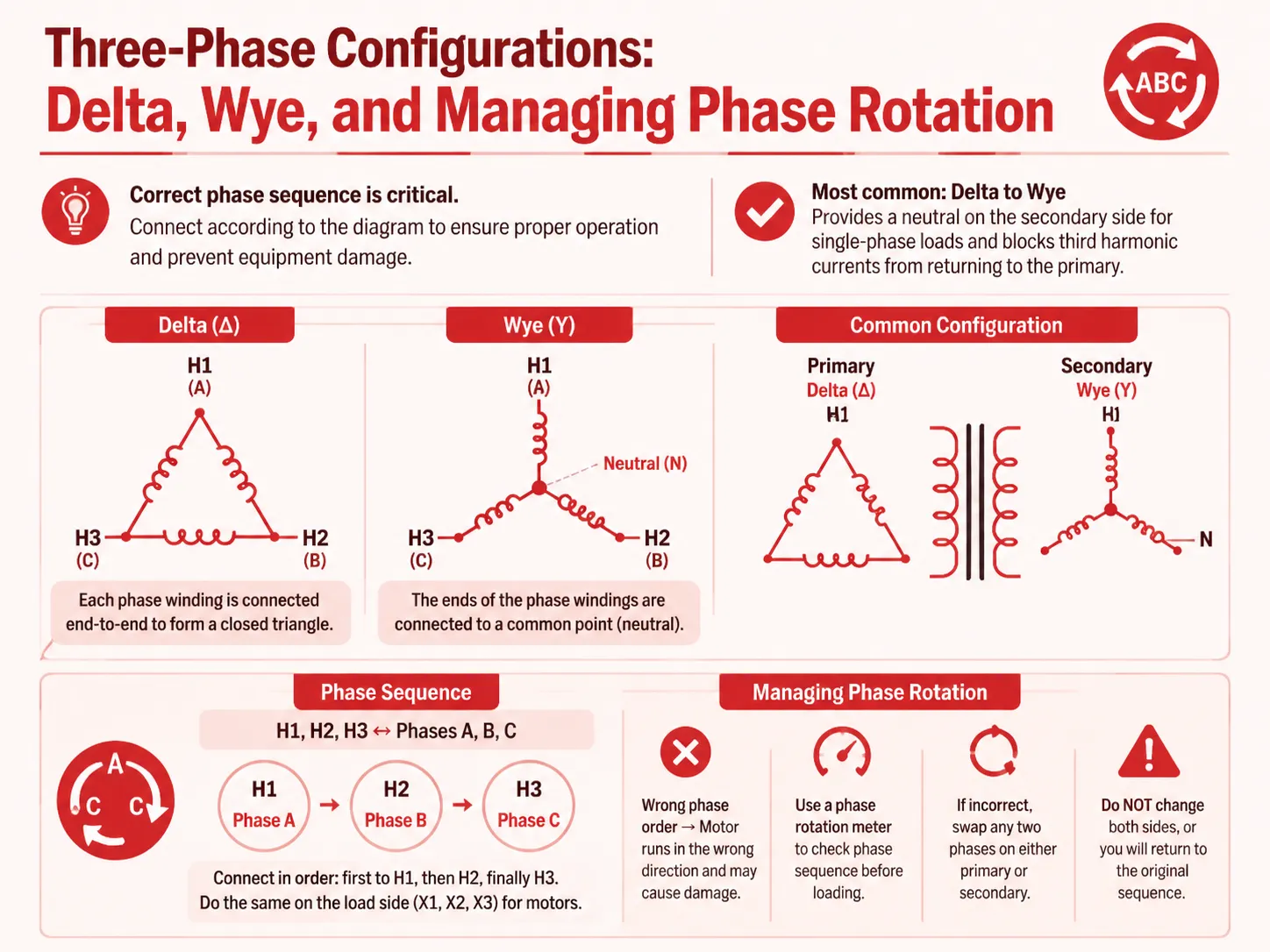
Correct phase sequence must be established for the wiring of three-phase transformers. A three-phase transformer can have either its primary connection be a delta (the end of each phase winding has been interconnected to form a closed triangle), or a wye (the end of each phase winding has an interconnected common point). Likewise, the secondary connection can be configured independently from the primary. The most common distribution transformer used is a delta to wye configuration, as it will provide a neutral on the secondary side of the transformer for the purpose of serving single-phase loads, while preventing the third harmonic currents from returning to the primary system.
The most critical step when connecting a 3-phase electrical unit is ensuring that the phases are connected according to the phase relationship illustrated on the connection diagram. H1, H2, and H3 correspond with Phases A, B, and C respectively. Therefore, if a specific phase rotation is required, the incoming electrical lines must be connected to H1, H2 and H3 (i.e., firstly to H1, then to H2, finally to H3). The identical procedure must be followed when connecting the X1, X2 and X3 on the load side of the transformer if the load has an electrical motor. If the three-phases are connected in the wrong order on either the load side of the transformer or the supply side to the transformer, the motor will rotate in the wrong direction which would lead to significant damage to pumps and compressors. A phase rotation meter should be used to check the phase sequence before loading is applied. If the phase rotation is incorrect, change from one to another on either the primary or secondary therefore reversing the three-phase sequence. However, do not change both because you will be back at where you started from.
Why Consistent Conductor Placement Is Critical for Safety
The H1 and H2 of a standalone transformer can be connected in either orientation, but maintaining consistency among all three phases of interconnected transformers is essential for proper operation; otherwise, an H1-X1 reversal of one transformer connected to an H2-X2 connected to another transformer in parallel with it would create a phase-to-phase fault on the secondary output voltage.
In addition to maintaining polarity, the secondary line-to-neutral and grounded conductors must also be connected to their respective terminals; thus, to avoid damaging equipment and creating hazards to personnel, there should never be any reverse line-neutral connections regardless of whether the grounded terminal has been identified as an effective neutral.
To help avoid such potentially dangerous and costly wiring errors when installing a transformer or transformer bank, always ensure that the identified grounded conductor is connected to the terminal identified as the neutral, and never connect the grounded conductor of any transformer or transformer bank to a terminal that was not designated as an effective bondable neutral by its manufacturer.
Maximizing Service Life Through Proper Load Management
Any good transformer wiring guide will also include some information regarding loading. The 80 percent rule was developed from the thermal limits of different insulation systems and can be thought of as a practical rule; that is, a transformer should not carry a continuous load that exceeds 80 percent of its nameplate kVA rating. This allows for additional headroom to accommodate for growth in load, harmonic heating from non-linear loads (such as VFDs or LED drivers) and simply because a transformer that runs cooler will tend to age much slower. IEEE C57.96 offers guidance on loading of dry-type transformers and states that for every 10°C that the hottest-spot temperature is over the rated insulation rating, the life expectancy of the transformer is approximately halved. The 80 percent rule is the easiest thermal management tool to apply because it doesn’t require complex instrumentation, calculations in the field, or anything other than a commitment not to overload the transformer.
Upon completion of your transformer and load connections, including all grounding connections, you should measure the phase current using a true-RMS clamp-on ammeter (clamp meter), additionally checking that no phase current is greater than 80% of the maximum rated current. If you find that any of the phases have currents that are around or exceeding this amount, you will need to consider either redistributing the load to resolve it, or installing a larger transformer. To assist you with selecting the correct kVA transformer prior to ordering, please refer to the Transformer Calculation Table for full-load current (IFL – Amperes) ratings corresponding to the most common transformer kVA ratings.
Field‑Proven Wiring Errors and How to Avoid Them
A lot of real-world experience in the factory and on the job identifies five main errors that cause most failures during the commissioning process for transformers:
- Loose connections: The feeling of a tight terminal will lead to heating, expansion, oxidation, and eventually, failure. Use a torque wrench at all times. The NECA 10 series guideline specifically recommends verification of torque for all bolted electrical connections.
- Tap changer set to the wrong position: If the primary voltage of a transformer delivered from the factory is high or low, you may want to adjust the tap on the transformer. Before energizing, make sure to check the supply voltage and adjust the tap accordingly.
- Ungrounded secondary neutral: A neutral conductor must always have a path to ground or “be bonded” at one point in these systems (i.e., very often at the service disconnect). If the system is set with a “floating neutral,” that creates unstable voltage and could potentially cause an overload or other problem (it is a serious safety hazard). NEC Article 250.30 requires that the system bonding jumper for separated derived systems be installed.
- Mixed phasing on parallel units: It’s essential for two transformers operating in parallel to connect their H1’s and X1’s in parallel for correct phasing; otherwise they will not be communicating consistently with each other. If one terminal is out of phase by just one terminal, it can create a current flow through both transformers (or “circulation currents”) that could potentially damage both units.
Each one of these mistakes can be eliminated by taking a systematic approach such as comparing the nameplate to the wiring diagram, verifying that all conductors are landed properly, and measuring both voltage and phase rotation before you close the load breaker.
Frequently Asked Questions
Does it matter which wire goes where on a transformer?
Yes, for secondary neutral connections, for polarity when paralleling or banking transformers, and for phase rotation on three‑phase systems. On a single isolated single‑phase transformer, the primary polarity does not affect function, but consistent marking is essential for safety and future maintenance.
What is the 80% rule for transformers?
The 80% rule states that a transformer should not be continuously loaded beyond 80% of its nameplate kVA rating. This practice protects the insulation system from accelerated thermal aging, provides capacity for load growth and harmonic currents, and is recommended by manufacturers for maximum service life.
How should a transformer be wired?
A transformer should be wired exactly according to the connection diagram on its nameplate, using conductors rated for the voltage and ampacity, terminated with the correct torque, and with all required bonding and grounding connections made. Always de‑energize and verify zero voltage before starting work, and measure voltage and phase rotation after energizing.
How to wire a 480 to 120 240 transformer?
For a single‑phase 480V primary to 120/240V secondary transformer, connect the 480V source to H1 and H2. On the secondary, the center‑tapped X0 is the neutral and must be bonded to ground. X1 to X0 gives 120V, X2 to X0 gives 120V, and X1 to X2 gives 240V. Torque all connections, megger the windings, and test voltage before connecting the load.
References
- Electrical Safety Foundation International (ESFI) — Home electrical safety data and distribution equipment failure statistics
- IEEE C57.12.00 — IEEE Standard for General Requirements for Liquid‑Immersed Distribution, Power, and Regulating Transformers
- NFPA 70 (NEC) Article 250 — Grounding and Bonding requirements for separately derived systems
- NFPA 70 (NEC) Article 250.30 — System bonding jumper requirements for separately derived systems
- National Electrical Contractors Association (NECA) — NECA 10‑series installation standards for electrical equipment torque verification
- IEEE C57.96 — IEEE Guide for Loading Dry‑Type Distribution and Power Transformers
Wiring a transformer is a task that rewards precision and punishes haste. The nameplate is your primary document. The terminal markings are a universal language. The torque wrench is the tool that keeps a tight connection from becoming a hot spot months or years later. Whether you’re landing conductors on a small dry‑type unit or commissioning a large distribution transformer, the sequence is the same: read, connect, torque, test. Done methodically, the installation will deliver reliable voltage transformation for decades.