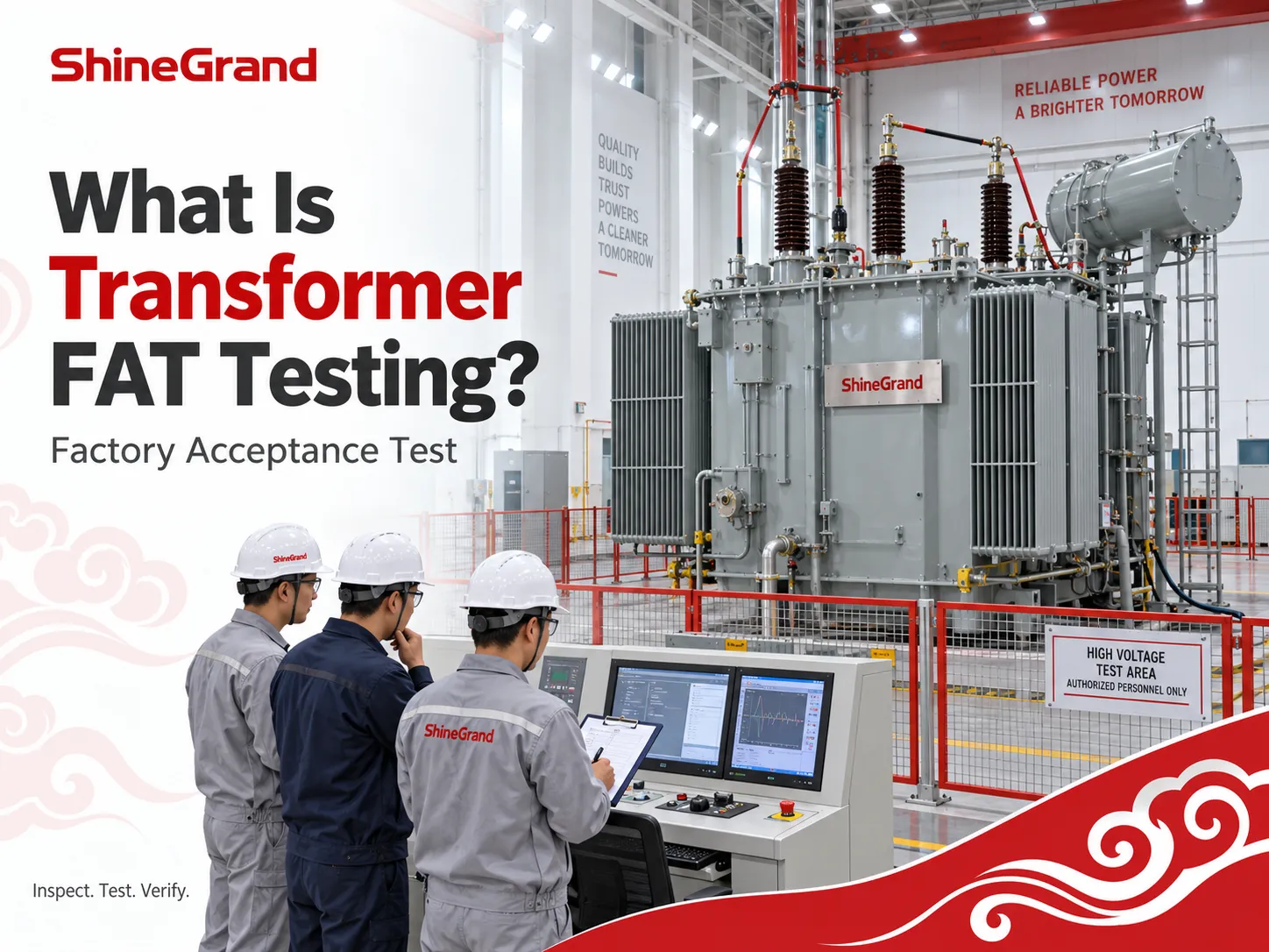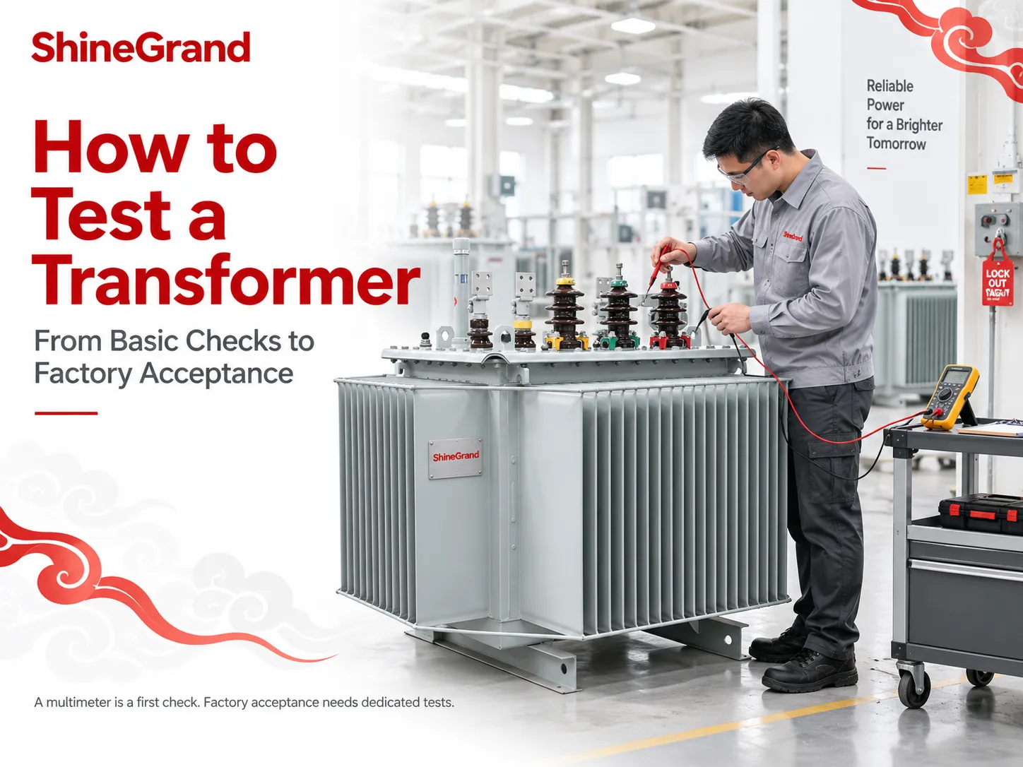
After manufacturing, the answer to how to test a transformer is to check its windings, voltage ratio, insulation, losses and impedance against the approved specification. Record the results against the unit’s serial number. Correct output voltage alone does not rule out a weak connection, defective insulation or excessive losses.
To test a finished transformer, verify its construction and connections, measure winding resistance and turns ratio, complete the required insulation and performance tests, and compare every result with the agreed acceptance limits. A multimeter helps identify basic faults; factory acceptance requires dedicated test equipment and a documented test report.
Transformer Test List: What Must Pass Before Shipment?
For power and distribution transformers, the test plan normally follows the applicable IEC 60076 or IEEE C57 requirements and the purchase specification. The exact scope depends on the design, voltage class and accessories. The following transformer test list shows what buyers should look for.
| Test or inspection | What it checks | Basis for acceptance |
|---|---|---|
| Visual, dimensional and nameplate inspection | Assembly, terminals, bushings, earthing provisions and specified fittings | Approved drawings and order requirements |
| Winding resistance | Winding continuity, joints and tap contacts | Design data and comparable phase/tap results at a common temperature |
| Voltage ratio, polarity and phase displacement | Correct turns, terminal identification and winding connections | Specified ratio and connection group, within applicable tolerances |
| Insulation resistance, where specified | Leakage through or across insulation | Approved test voltage, duration, temperature and resistance criteria |
| Applied and induced voltage withstand | Insulation strength under the prescribed electrical stress | Required test sequence completed without insulation failure |
| No-load loss and current | Core performance at the specified voltage and frequency | Guaranteed values and permitted tolerances |
| Load loss and short-circuit impedance | Losses under current and the transformer’s impedance | Guaranteed values, corrected to the specified reference temperature |
| Design-specific checks | Oil condition and tightness, partial discharge, cooling controls or protection accessories | Requirements applicable to that transformer |
Routine tests are designed to assess individual pieces of equipment. Temperature-rise tests fall into the category of type tests. Different equipment classes may require partial discharge tests, but routine test requirements differ by class of equipment. Inquire about results pertaining to the unit being supplied, as well as results from the type test applicable to the equipment configuration. SGB-SMIT’s planning guide illustrates this distinction for cast-resin transformers.
How to Test a Transformer Without Power Using a Multimeter
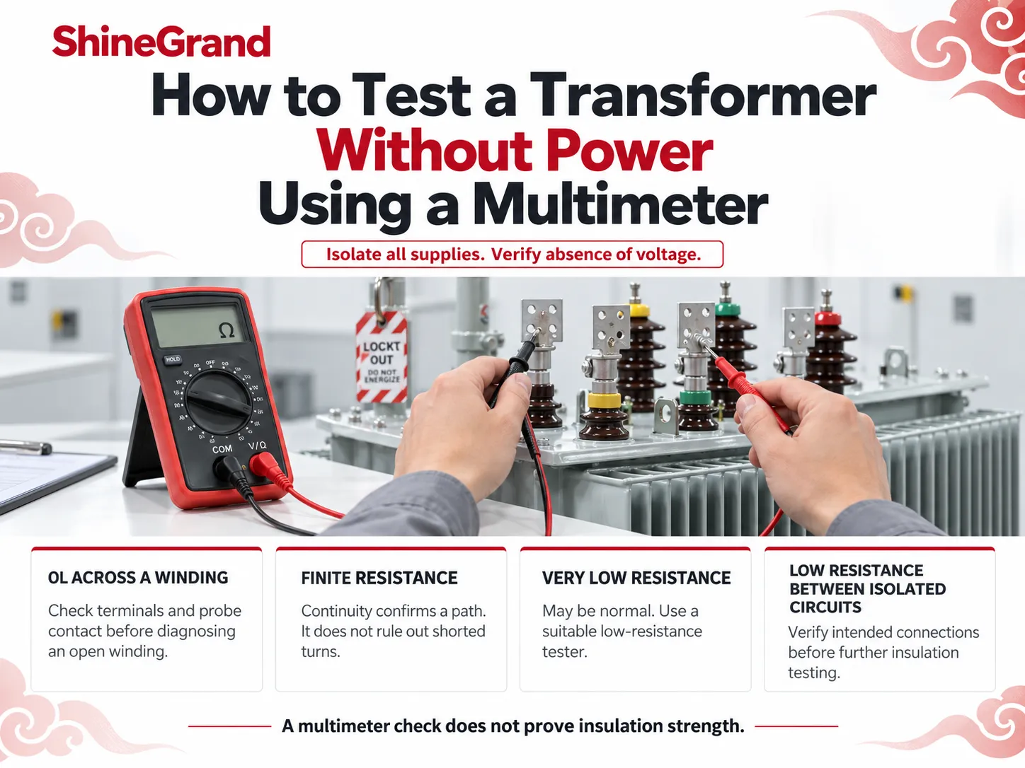
To test a transformer without power, the first thing to do is to consult the terminal diagram and isolate the supply circuits. You must ensure that all circuits are locked, checked for voltage and then discharged and grounded. External circuits affecting the result of the measurement must be disconnected, and the resistance mode must not be used in the energized circuit.
To check transformer primary and secondary windings, you should measure each winding separately at its terminals and use the designated tap connection, not only the wire color and location.
| Multimeter result | What it may mean | What to check next |
|---|---|---|
| OL across a winding expected to be continuous | Open winding, loose lead, open thermal protector or incorrect terminals | Confirm the diagram and probe contact before diagnosing winding damage |
| Finite resistance across each winding | A conductive path exists | Compare with design data; continuity does not exclude shorted turns |
| Very low resistance | May be normal for a heavy, low-voltage winding | Use a suitable low-resistance instrument; do not declare a short from the beep alone |
| Low resistance between circuits intended to be isolated | Possible insulation fault or an external/intentional connection | Verify the design and isolation before further insulation testing |
Final measurement is ineffective in autotransformers because it has one common winding (or one with intentional earthing). At the same time, OL between isolated windings on the multimeter is only indicative of the presence of a fault, without giving any information on insulation resistance.
To test transformer windings accurately in the factory, the readings should be recorded after they achieve stationarity, and the winding temperature should also be recorded. The results obtained shall be corrected. It is necessary to wait for a complete discharge of the apparatus before removing the leads, as during the DC test windings are charged. Megger explains these measurement and discharge requirements.
How to Test Transformer Voltage and Turns Ratio
In a factory, a transformer turns ratio (TTR) tester checks the specified ratios and connections across the required taps and phases. For a simple single-phase transformer at no load, primary voltage ÷ secondary voltage ≈ primary turns ÷ secondary turns. Three-phase testing must account for the winding connection and phase displacement; dividing two nameplate line voltages is not always the winding turns ratio.
For a small control transformer, a qualified technician can test transformer output voltage with a suitably rated multimeter set to AC volts. Measurements are taken across the specified terminal pair, with input supply and load condition recorded. Do not assume either secondary terminal is earth. Factory and high-voltage tests require a controlled test installation.
| Voltage result | Likely direction of investigation | Useful distinction |
|---|---|---|
| Missing or incorrect primary voltage | Supply, fuse, wiring or selected input tap | The transformer has not yet been shown to be faulty |
| Correct input but absent or abnormal unloaded output | Connections, protection devices, winding integrity and ratio | Check against the specified no-load output |
| Output acceptable unloaded but low under load | Excess load, downstream short, wiring drop or a transformer defect | Compare load current with rated output current, or compare calculated load VA with the VA rating |
A nominal 24 VAC heater or HVAC transformer does not have to show exactly 24 volts. The output depends on the supply voltage and load. For a TTR test, the allowed deviation ratio depends on the standards used, the design of the transformer, and the tap. See Fluke’s control-voltage guidance and Megger’s ratio-testing explanation.
How to Test a Doorbell Transformer
If you need to find out how to test a doorbell transformer, start with its secondary rated AC voltage, and determine the voltage and VA ratings of the doorbell used. Moreover, a proper voltage check does not mean that the transformer has a capacity sufficient to power the doorbell.
A skilled technician uses a multimeter to take the measurement between two pairs of terminals of the transformer that have voltage ratings. This should be performed while making sure mains connections are properly housed. The technician compares the readings taken with the manufacturer’s specification for the operating conditions specified. The transformer should be switched off and disconnected before taking any actions.
There may be a wiring fault in case the voltage is normal at the transformer, but practically absent at the doorbell. If however the voltage decreases at the moment of doorbell activation, the load and power source have to be checked. Google Nest’s compatibility guide explains model-specific voltage and power requirements.
How to Test a Transformer with a Megger
When you want to test a transformer with a megger, you should use a megohm meter and follow the guidelines related to the connections and range of megger voltage and duration for the specified transformer. The instrument checks the insulation resistance of the transformer by the applied test voltage. The transformer tester should be disconnected from the transformer and all appropriate accessories should be handled as specified in the approved test procedure.
| Insulation test | What the result tells you | Important limitation |
|---|---|---|
| Insulation resistance | Resistance between specified winding groups and between windings and earth | Temperature, moisture and surface contamination affect the reading; there is no universal pass value |
| Applied and induced voltage withstand | Whether insulation survives the prescribed AC test stress | A high megohm reading cannot replace these tests |
| Oil breakdown voltage (BDV) | The dielectric breakdown strength of a sampled insulating liquid | It evaluates the sample, not the transformer’s entire insulation system |
After you perform tests, make sure to record the test voltage, duration time, temperature, and insulation reading. After that, make sure that the equipment discharges completely before making a safe assumption regarding the ability to touch the connections. Fluke’s insulation-tester guide explains why instrument selection and test voltage matter.
To test transformer oil breakdown voltage, a laboratory tests the sample under specified conditions using a dedicated oil-testing set. The method defined, such as IEC 60156 or the required ASTM method, defines the configuration of electrodes and the testing sequence. The acceptance criteria depends on the project and fluid specifications. Saying the breakdown voltage in kV without specifying the method used is unreasonable. Megger’s oil-testing guidance covers the method-dependent setup.
What Loss and Temperature-Rise Tests Tell You
Understanding the meaning of the term extract transform load testing involves looking at ETL in terms of software data pipeline checks and not in relation to transformers and the electrical aspect; IBM’s ETL overview explains the data-processing meaning.
The open-circuit test measures no-load loss and current. The test source gives the power to one coil through the use of the required voltage and the frequency while ensuring that the other coil is not connected to the circuit. The results from the test show the presence of losses which necessitate the assessment of the core and the conditions of testing. The open phase will imply that the current induced is in place.
The short circuit test relates to load losses and impedances observed. The test is done in controlled areas whereby one phase will be short connected while the other phase will be subjected to the reduction until the required current limit for the test is attained. The load loss is made up of the winding and losses that occur due to other factors. This test does not involve short circuiting the supply and also requires that when making the test no phase is directly shorted.
The temperature-rise test verifies thermal performance. Winding and, where applicable, oil temperatures are evaluated against the design limits. Depending on transformer capacity, the laboratory may use actual loading, a back-to-back arrangement or an equivalent loading method. The report should identify the method and required temperature corrections.
For the temperature rise test, the results will tell whether the thermal process has occurred. The winding and oil temperatures are reviewed in terms of what is stated in design specifications. The size of the transformer determines the method that can be used to conduct the tests. HIOKI describes these measurements and temperature-rise methods.
What a Transformer Test Report Should Include
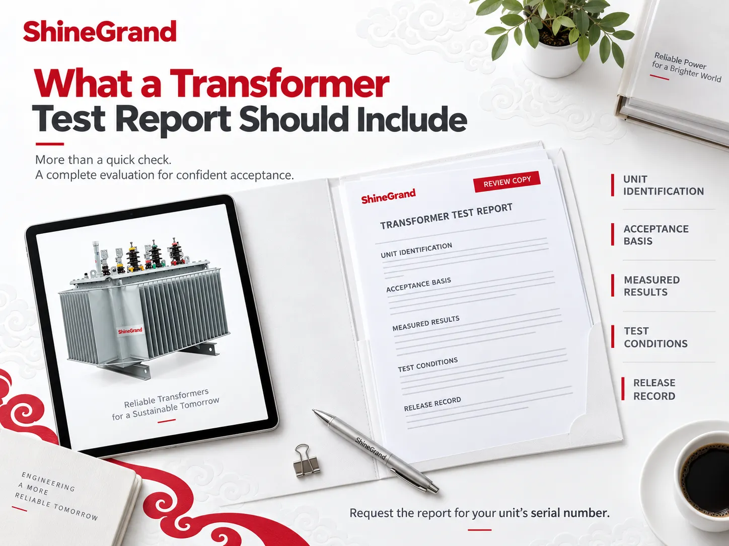
A “PASS” stamp is useful only when you can see what passed. Before accepting delivery, check that the report identifies the actual transformer and shows the conditions needed to interpret its results.
| Report item | What to look for | Why it matters |
|---|---|---|
| Unit identification | Serial number, rating, voltages, frequency, connection group and taps | Connects the results to the supplied equipment |
| Acceptance basis | Applicable standard and edition, approved specification and limits | Makes pass/fail decisions auditable |
| Measured results | Values, units, tap/phase identification and relevant corrections | Allows technical comparison instead of relying on a checkbox |
| Test conditions and instruments | Temperature, test voltage/current/frequency, duration and calibration traceability as applicable | Shows whether measurements are comparable and trustworthy |
| Release record | Test date, authorization, resolved deviations and relevant type-test references | Confirms that outstanding issues have been addressed |
In order to obtain a transformer testing PDF, you must request for the factory report that corresponded to the serial number you are dealing with. A general description of the testing process or a sample certificate is not sufficient proof of the fact that the unit passed the inspection. Keep the original report for future use in commissioning and maintenance of the transformer.
What Happens If a Transformer Fails a Test?
The equipment must be held for inspection. The first step is to confirm the configuration, materials, interconnections and temperature adjustment of the apparatus. If it still does not function properly, fix the malfunction and rerun not only the affected tests, but also any other tests necessary according to repair and procedure rules. The fact that another measurement provides a reading within the limit does not justify accepting the first result.
When ordering testing from ShineGrand Electric, make sure to specify what testing standard should be used, the acceptance limits, documentation for the report and requirements for the witness test in the quote stage. This way the supplier and the customer will be well informed about what needs to be done after the transformer leaves the manufacturer.
References
- Ampheo — Testing Transformers with a Multimeter: A Comprehensive Guide. Background on basic voltage checks and troubleshooting.
- HIOKI — How to Test a Transformer. Instrument-based evaluation, inductance measurements and temperature-rise testing.
- Meta Power Solutions — How to Test a Transformer. Overview of open-circuit, short-circuit and winding resistance test purposes.
- SGB-SMIT — Routine Tests for Dry-Type Transformers. Test methods, acceptance criteria and sample test documentation.
- SGB-SMIT — Cast-Resin Transformer Planning Guide. Routine, type and special testing for cast-resin designs.
- Megger — Winding Resistance Testing and Transformer Turns Ratio Testing. Measurement interpretation, temperature effects and test precautions.
- Fluke — Choosing an Insulation Resistance Tester and HVAC Electrical Testing Applications. Insulation-test selection and nominal 24 VAC control-voltage checks.
- Megger — Insulating Oil Test Sets and Testing Guidance. Oil breakdown testing, sampling considerations and standard test methods.
- Schneider Electric — 80% and 100% Rated Breakers and E.ON — Power Transformer Technical Requirements. Context for continuous-load limits and transformer rated operation.
- Maddox — Why Transformers Hum and Hitachi Energy — Power Transmission Transformers. Normal transformer sound and long-term service context.
- Google Nest — Doorbell Compatibility. Transformer AC voltage, VA ratings and doorbell wiring measurements.
- IBM — What Is ETL?. The extract, transform and load process used in data pipelines.
FAQ
How can I test if a transformer is bad?
When deciding how to test a transformer for a suspected fault, check the supply and connected load first. With the unit safely isolated, inspect it and test winding continuity. Qualified personnel can then check ratio, insulation and output under the specified conditions. A correct output voltage alone cannot confirm that insulation and thermal performance are acceptable.
How to test a transformer without power using a multimeter?
To test a transformer with a multimeter in resistance mode, isolate it, verify absence of voltage and disconnect external paths that affect readings. Measure across each identified winding. An unexpected open circuit needs investigation. A continuity beep only confirms a path; it does not rule out shorted turns or replace an insulation test.
What are the signs that a transformer is bad?
Burning smell, damaged insulation, leakage, repeated protective trips, excessive temperature and abnormal output are warning signs. A new or changing noise also deserves investigation. A steady hum can be normal, and the cause of a trip may be outside the transformer.
How to check a good transformer?
A good transformer meets its specified electrical and thermal requirements. Confirm acceptable winding, ratio, insulation and loss results, together with any design-specific checks. Without a multimeter, visual inspection can find damage, but appearance alone cannot establish that it works; suitable test instruments and records are still needed.
What is the 80% rule for transformers?
It usually means allowing capacity headroom by planning around 80% of rated kVA. It is not a universal transformer operating limit or factory acceptance rule. Permitted loading follows the nameplate, cooling and service conditions. The 80% continuous-load limit associated with standard-rated circuit breakers is a separate equipment-rating issue.
How to tell if a 24 volt transformer is bad?
To test a 24 volt transformer, a qualified technician checks the rated AC input and compares the secondary reading with the manufacturer’s output specification. If output falls under load, investigate excess VA demand, a downstream short or wiring loss. Nominal 24 VAC need not measure exactly 24.0 V, particularly without load.
What is the most common cause of transformer failure?
There is no single ranking that applies to every transformer population. Winding insulation deterioration is a major failure mechanism, accelerated by heat and moisture. Bushings, tap changers, connections and cooling equipment can also fail. Diagnosis should identify the failed component and its underlying cause.
What is the average lifespan of a transformer?
There is no useful average covering everything from small control transformers to utility power units. Power transformers can operate for decades; Hitachi Energy describes service life of up to 40 years for its power-transmission application. Actual life depends on insulation condition, loading, cooling, environment and maintenance.
How do you know if a transformer has blown?
A bang, smoke or loss of supply may indicate an electrical fault, but a blown fuse alone does not prove the transformer has failed. Keep away from damaged equipment and have qualified personnel isolate and diagnose it before re-energizing. Microwave transformers and their associated high-voltage circuits require specialist service.
Conclusion
Knowing how to test a transformer means knowing which measurements confirm that it meets the specification. Use a multimeter for basic fault checks, dedicated instruments for acceptance measurements, and the serial-number-specific report to confirm what passed before shipment.