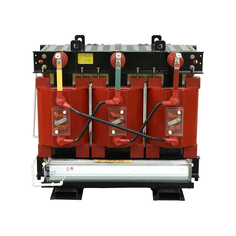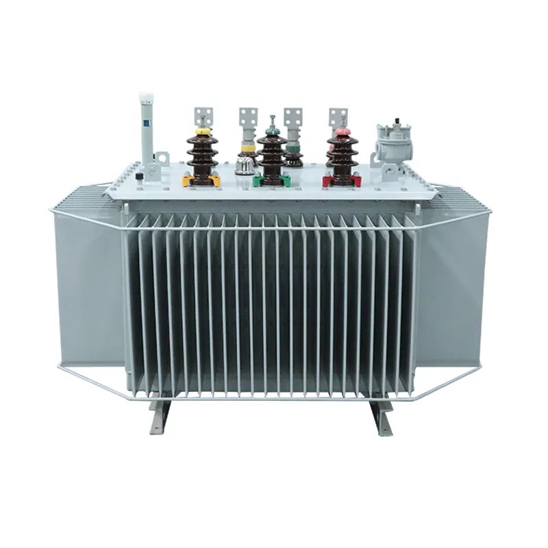
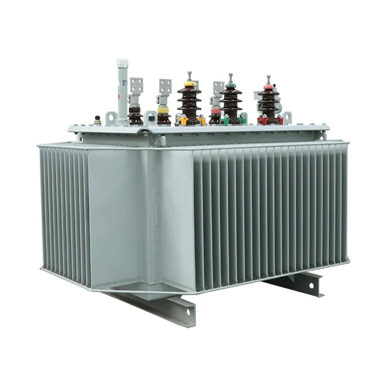
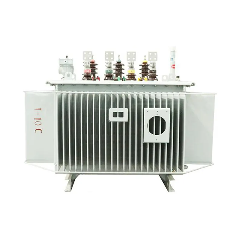
Introduction into the 6-10kV High-Efficiency Oil-Type Distribution Transformer
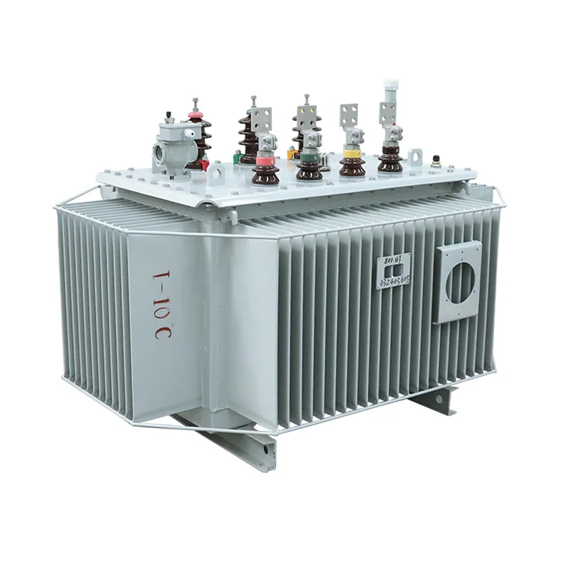
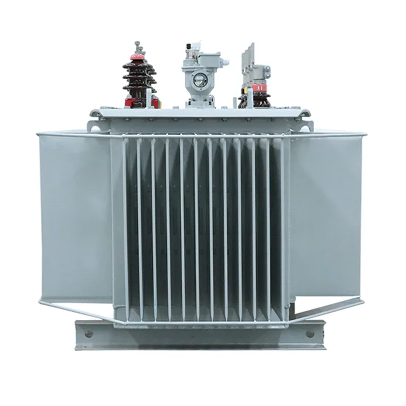
The 6-10kV oil-type distribution transformer is designed for medium voltage power distribution with exceptional efficiency. Engineered with high-grade cold-rolled silicon steel cores and multi-layer oxygen-free copper windings, this oil immersed transformer reduces no-load and load losses, lowering energy consumption and operational costs. The fully sealed corrugated tank prevents oil contamination and aging, ensuring extended service life with minimal maintenance.
This transformer reliably operates under standard climate conditions, altitude up to 1000 meters, and temperatures ranging from -25°C to +40°C, adhering to GB/T and IEC 60076 standards. Available in S11 and S13 series configurations, it offers scalable solutions for utilities, industrial plants, and renewable energy connections.
- Rated primary voltage: 6kV or 10kV, three-phase 50Hz operation.
- S13 series features ultra-low-loss design, reducing no-load losses by 20-30% compared to S11 models.
- Fully sealed corrugated tank enhances safety and compactness.
- Connection options: Dyn11, Yzn11, or Yyn0, with ±2×2.5% or ±5% tap range.
Benefits and Key Advantages of 6-10kV Oil-Type Distribution Transformers
Energy Savings
Reduced no-load and load losses in S11 and S13 models ensure minimal electricity waste and lower annual operating costs.
Enhanced Durability
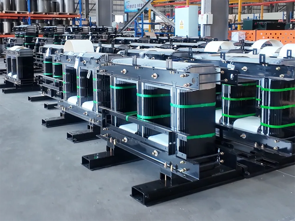
Spiral winding design and improved coil support increase mechanical strength and thermal stability during short-circuit conditions.
Low Maintenance
Fully sealed corrugated tank prevents oil aging and external contamination, extending maintenance intervals.
High Reliability
Rigorous material selection — oxygen-free copper and premium silicon steel — ensures consistent performance under varying loads.
Transport Safety
Reinforced lifting lugs and positioning brackets enable secure handling and installation at various sites.
Standards Compliant
Fully aligned with GB/T, IEC 60076, and related national standards for broad acceptance across utility projects.
Uses & Industries
Industrial Manufacturing
Supplies reliable power to heavy machinery and processing lines, with high overload tolerance.
Commercial & Large Facilities
Ideal for office towers, shopping malls, and hospitals due to its compact and quiet design.
Renewable Energy Integration
Steps up voltage from solar or wind farms for grid connection, ensuring minimal energy loss and maximum efficiency.
Rural & Urban Distribution
Perfect for medium-voltage networks in residential areas and remote electrification projects.
Technical Data & Specifications
6kV and 10kV S11 and S13 series oil-immersed non-excitation voltage regulating distribution transformer parameters. Custom configurations available.
S11 Series Parameters
| Rated Capacity (kVA) | High Voltage (kV) | Tap Range | Low Voltage (kV) | Connection | No-load Loss (kW) | Load Loss (kW) | Impedance (%) | Total Weight (kg) | Dimensions L*W*H (mm) | Gauge (mm) |
|---|---|---|---|---|---|---|---|---|---|---|
| 30 | 6; 6.3; 10; 10.5 | ±2×2.5% ±5% | 0.4 | Dyn11 Yzn11 Yyn0 | 0.100 | 0.630/0.600 | 4.0 | 325 | 680*480*846 | 550/400 |
| 50 | Dyn11 Yzn11 Yyn0 | 0.130 | 0.910/0.870 | 4.0 | 435 | 765*690*876 | 550/400 | |||
| 63 | Dyn11 Yzn11 Yyn0 | 0.150 | 1.09/1.04 | 4.0 | 490 | 795*645*915 | 550/400 | |||
| 80 | Dyn11 Yzn11 Yyn0 | 0.180 | 1.31/1.25 | 4.0 | 550 | 825*660*925 | 550/550 | |||
| 100 | Dyn11 Yzn11 Yyn0 | 0.200 | 1.58/1.50 | 4.0 | 590 | 810*770*890 | 550/550 | |||
| 125 | Dyn11 Yzn11 Yyn0 | 0.240 | 1.89/1.80 | 4.0 | 660 | 825*800*960 | 550/550 | |||
| 160 | Dyn11 Yzn11 Yyn0 | 0.280 | 2.31/2.20 | 4.0 | 720 | 1115*735*985 | 550/550 | |||
| 200 | Dyn11 Yzn11 Yyn0 | 0.340 | 2.73/2.60 | 4.0 | 790 | 1186*815*1050 | 550/550 | |||
| 250 | Dyn11 Yzn11 Yyn0 | 0.400 | 3.20/3.05 | 4.0 | 960 | 1290*860*1050 | 660/660 | |||
| 315 | Dyn11 Yzn11 Yyn0 | 0.480 | 3.83/3.65 | 4.0 | 1120 | 1350*920*1090 | 660/660 | |||
| 400 | Dyn11 Yzn11 Yyn0 | 0.570 | 4.52/4.30 | 4.0 | 1440 | 1485*1030*1120 | 660/660 | |||
| 500 | Dyn11 Yzn11 Yyn0 | 0.680 | 5.41/5.15 | 4.0 | 1800 | 1485*1030*1160 | 660/660 | |||
| 630 | Dyn11 Yyn0 | 0.810 | 6.20 | 4.5 | 1770 | 1550*1045*1225 | 660/660 | |||
| 800 | Dyn11 Yyn0 | 0.980 | 7.50 | 4.5 | 2060 | 1730*1220*1285 | 820/820 | |||
| 1000 | Dyn11 Yyn0 | 1.150 | 10.3 | 4.5 | 2505 | 1670*1160*1375 | 820/820 | |||
| 1250 | Dyn11 Yyn0 | 1.360 | 12.0 | 4.5 | 2970 | 1750*1240*1425 | 820/820 | |||
| 1600 | Dyn11 Yyn0 | 1.640 | 14.5 | 4.5 | 3950 | 1860*1250*1485 | 820/820 | |||
| 2000 | Dyn11 Yyn0 | 1.940 | 18.3 | 5.0 | 4305 | 1990*1315*1620 | 820/820 | |||
| 2500 | Dyn11 Yyn0 | 2.290 | 21.2 | 5.0 | 5440 | 2065*1360*1750 | 1070/1070 |
S13 Series Parameters (Ultra-Low-Loss)
| Rated Capacity (kVA) | High Voltage (kV) | Tap Range | Low Voltage (kV) | Connection | No-load Loss (kW) | Load Loss (kW) | Impedance (%) | Total Weight (kg) | Dimensions L*W*H (mm) | Gauge (mm) |
|---|---|---|---|---|---|---|---|---|---|---|
| 30 | 6; 6.3; 10; 10.5 | ±2×2.5% ±5% | 0.4 | Dyn11 Yzn11 Yyn0 | 0.080 | 0.630/0.600 | 4.0 | 280 | 700*545*855 | 550/400 |
| 50 | Dyn11 Yzn11 Yyn0 | 0.100 | 0.91/0.87 | 4.0 | 370 | 750*645*915 | 550/400 | |||
| 63 | Dyn11 Yzn11 Yyn0 | 0.110 | 1.09/1.04 | 4.0 | 440 | 790*645*915 | 550/400 | |||
| 80 | Dyn11 Yzn11 Yyn0 | 0.130 | 1.31/1.25 | 4.0 | 480 | 805*706*930 | 550/550 | |||
| 100 | Dyn11 Yzn11 Yyn0 | 0.150 | 1.58/1.50 | 4.0 | 600 | 850*685*1075 | 550/550 | |||
| 125 | Dyn11 Yzn11 Yyn0 | 0.170 | 1.89/1.80 | 4.0 | 645 | 850*790*975 | 550/550 | |||
| 160 | Dyn11 Yzn11 Yyn0 | 0.200 | 2.31/2.20 | 4.0 | 790 | 880*860*1050 | 550/550 | |||
| 200 | Dyn11 Yzn11 Yyn0 | 0.240 | 2.73/2.60 | 4.0 | 870 | 1180*791*1090 | 550/550 | |||
| 250 | Dyn11 Yzn11 Yyn0 | 0.290 | 3.20/3.05 | 4.0 | 1050 | 1270*850*1140 | 660/660 | |||
| 315 | Dyn11 Yzn11 Yyn0 | 0.340 | 3.83/3.65 | 4.0 | 1150 | 1320*900*1160 | 660/660 | |||
| 400 | Dyn11 Yzn11 Yyn0 | 0.410 | 4.52/4.30 | 4.0 | 1370 | 1390*950*1215 | 660/660 | |||
| 500 | Dyn11 Yzn11 Yyn0 | 0.480 | 5.41/5.15 | 4.0 | 1680 | 1420*950*1280 | 660/660 | |||
| 630 | Dyn11 Yyn0 | 0.570 | 6.20 | 4.5 | 1960 | 1490*1000*1340 | 660/660 | |||
| 800 | Dyn11 Yyn0 | 0.700 | 7.50 | 4.5 | 2150 | 1640*1155*1350 | 820/820 | |||
| 1000 | Dyn11 Yyn0 | 0.830 | 10.3 | 4.5 | 2410 | 1660*1155*1380 | 820/820 | |||
| 1250 | Dyn11 Yyn0 | 0.970 | 12.0 | 4.5 | 2860 | 1720*1250*1480 | 820/820 | |||
| 1600 | Dyn11 Yyn0 | 1.170 | 14.5 | 4.5 | 3745 | 1840*1340*1560 | 820/820 | |||
| 2000 | Dyn11 Yyn0 | 1.550 | 18.3 | 5.0 | 4289 | 2010*1370*1660 | 820/820 | |||
| 2500 | Dyn11 Yyn0 | 1.830 | 21.2 | 5.0 | 5170 | 2020*1370*1850 | 1070/1070 |
Contact us for detailed dimension drawings, efficiency curves, and customization options for specific high-altitude or tropical conditions.
Why Buy Our 6-10kV High-Efficiency Oil-Type Distribution Transformer
Proven Energy Savings
Both S11 and S13 series deliver industry-leading low losses, cutting operational costs significantly over the transformer’s 30-year life.
Certified Quality
Each unit is tested per IEC 60076 and GB/T standards: winding resistance, insulation, and no-load/load loss verification.
Competitive Pricing
Factory-direct supply of oil-type distribution transformers ensures cost-effective procurement for bulk utility projects.
Fast Lead Times
Standard S11 models ship in 4–6 weeks; S13 ultra-low-loss units in 6–8 weeks. Flexible delivery for urgent needs.
Certifications & Standards
Why Buy Our 6-10kV High-Efficiency Oil-Type Distribution Transformer
Proven Energy Savings
S11 and S13 series offer industry-leading low losses, significantly reducing operational costs over a 30-year lifespan.
Certified Quality
Tested under IEC 60076 and GB/T standards for insulation, winding resistance, and loss accuracy.
Competitive Pricing
Factory-direct supply ensures cost-efficient procurement suitable for large-scale projects.
Fast Lead Times
S11 models ship within 4–6 weeks; S13 units within 6–8 weeks, with expedited delivery available.
Certifications & Standards
GB/T 1094
ISO 9001
CE
DOE 2016
How This Oil-Type Distribution Transformer Fits Your Project
Guidance for utilities, EPCs, and contractors selecting 6-10kV high-efficiency distribution transformers.
Project Applications
For Industrial Grids, the 630–2500kVA range powers heavy equipment with reliable voltage regulation. In Renewable Energy Parks, the ultra-low-loss S13 series preserves energy yield for solar and wind grid connections. Urban Distribution Networks benefit from the compact sealed design and low noise, integrating easily into building-adjacent substations.
S11 vs S13 — Choosing the Right Efficiency Level
The S11 series offers excellent cost-efficiency for standard projects. For long-term energy savings, the S13 ultra-low-loss series reduces no-load losses by 20–30%, paying back the incremental investment within a few years. Both series are available in the same capacities and voltage ratings, with the same durable sealed tank construction.
Sizing and Configuration
Select capacity based on total load (kVA) following the recommended 35–40% average annual load rate for maximum efficiency. Connection group Dyn11 is standard for three-phase distribution; Yzn11 or Yyn0 are also available. Custom secondary voltages and special gauges can be supplied on request.
Frequently Asked Questions
What is the 80% rule for transformers?
The 80% rule recommends not loading a transformer continuously above 80% of its nameplate kVA rating to prevent overheating and extend insulation life. It is a best practice aligned with NEC continuous load guidelines.
What’s the difference between a power transformer and a distribution transformer?
A power transformer operates at high voltages (above 35kV) for transmission networks and is designed for high efficiency at full load. A distribution transformer steps down medium voltage (6-10kV) to utilization voltage (0.4kV) and is optimized for efficiency at varying, lower average loads.
How many amps is a 10 kVA transformer?
For a three-phase 400V secondary, a 10 kVA transformer delivers approximately 14.4A (I = 10kVA / (1.732 × 0.4kV)). The exact current depends on the specific secondary voltage. Our 30–2500kVA range covers much larger loads.
How do you size a distribution transformer?
Calculate the total connected load (kW) and convert to kVA using the power factor. Add safety margin for future expansion. For best efficiency, size the transformer so the average load is 35–40% of its rated capacity, as noted in the technical tables.