When energy is produced at the Batangas coal power plant, the voltage it generates (13.8 kV) is too low to move through the power lines of Luzon. The amount of electricity would be unmatched; some copper losses will happen, and the voltage will drop below normal before reaching the first substation. The answer is found in the electrical substation right near the generating station: the step-up transformer – an electrical appliance that increases the voltage of electricity up to 230 or 500 kV. Without this apparatus, the energy produced in a province would not be transmitted and used in another location far away. It is important to understand the function of a step-up transformer and the difference between it and a step-down transformer as this becomes the basis for the discussions about power generation and transmission.
The Core Function: Raising Voltage, Reducing Current, Minimising Losses
A transformer that increases its input voltage from primary (input) winding to secondary (output) winding is called a step-up transformer. The voltages increase and currents decrease. Power remains constant, except for a certain amount of loss in the core and windings. This current-voltage relationship is the basis for the operation of the transformer and is essentially the whole point of having one. Power is the product of voltage and current. When transmitting power over a long distance that requires low voltage, a high current is needed which causes significant power loss because of the high current. Expressed differently, in transmission line losses increase with the square of the current. If the voltage doubles, then the current reduces by a factor of two as well and losses decrease by a factor of four. This is the reason for the efficiency of high voltage transmission. The step-up transformer makes it possible at the generation side of the electric grid. The step-down transformer at the consumption side reduces the voltage back to the level usable in households, factories, and business facilities.The two devices are inverse functions of each other, and both are essential. Resources from the U.S. Department of Energy explain the role of transformers in the grid, and the fundamental principle of voltage‑current transformation is defined in transformer theory by the turns ratio: the ratio of secondary turns to primary turns determines whether the transformer steps the voltage up (more secondary turns) or down (fewer secondary turns).
How a Step‑Up Transformer Differs from a Step‑Down Transformer
From a physical point of view, both the step-up transformer and step-down transformer basically look the same since both use the same materials. Both types of transformers use steel cores and copper or aluminum windings along with gaskets and tanks. The only difference between the two types of transformers is that the step-up transformer has more turns in its secondary winding than in the primary. A step-down transformer therefore has fewer turns that allow it to get a lower output voltage. It is possible to reverse the functions of the two transformers and operate them in reverse. All you need to do is to energize the transformer which is typically used for secondary winding so that it works as the primary (while reducing the voltage). Nevertheless, the step-up transformer is specially designed to withstand the high voltage loads of step-up applications and has a different winding technique (in most cases a delta-wye type of winding).
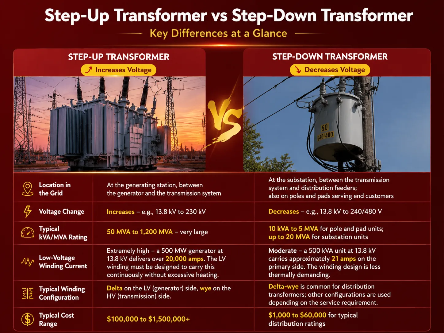
The table presented below highlights the main distinctions made between a step-up transformer and its opposite, the step-down transformer.
| Characteristic | Step‑Up Transformer | Step‑Down Transformer (Distribution) |
|---|---|---|
| Location in the grid | At the generating station, between the generator and the transmission system | At the substation, between the transmission system and the distribution feeders; also on poles and pads serving end customers |
| Voltage change | Increases — e.g., 13.8 kV to 230 kV | Decreases — e.g., 13.8 kV to 240/480 V |
| Typical kVA/MVA rating | 50 MVA to 1,200 MVA — very large | 10 kVA to 5 MVA for pole and pad units; up to 20 MVA for substation units |
| Low‑voltage winding current | Extremely high — a 500 MW generator at 13.8 kV delivers over 20,000 amps. The LV winding must be designed to carry this continuously without excessive heating. | Moderate — a 500 kVA unit at 13.8 kV carries approximately 21 amps on the primary side. The winding design is less thermally demanding. |
| Typical winding configuration | Delta on the LV (generator) side, wye on the HV (transmission) side. The delta traps zero‑sequence harmonics from the generator; the wye provides a neutral for the transmission system. | Delta‑wye is common for distribution transformers; other configurations are used depending on the service requirement. |
| Typical cost range | $100,000 to $1,500,000+ | $1,000 to $60,000 for typical distribution ratings |
Where Step‑Up Transformers Are Used
The most common instance of a step-up transformer is in the generating station, the GSU (generator step-up) transformer, which connects a coal, gas, nuclear, hydro, or wind turbine generator to the grid. Each major power plant around the world has at least one GSU; in a big plant, there could be one for every generating unit. The GSU is a specially-designed machine since it needs to be compatible with the generator’s voltage and the required transmission voltage, and it adjusts the impedance to balance the requirements of the current limit and voltage regulation.Our guide on what a GSU transformer is provides a detailed technical reference for this specific and demanding application.
In addition to power generating stations, step-up transformers find application in several more cases. Among renewable energy installations like wind farms, solar farms or battery systems, the inverter generates electricity at a low or medium voltage level (usually between 480V and 690V for solar systems; between 690V and 12kV for wind turbines). The electricity from the generator is transmitted to a step-up transformer which elevates its voltage up to the level required for a collection system (usually 34.5kV) and for transmission. When it comes to industrial places utilizing powerful motors working at either 4.16kV or 13.8kV, step-up transformers can be used to convert voltage levels from utility level to the operational level of motors. This type of transformer is also useful in laboratories and testing facilities for the generation of high voltage levels used for dielectric testing or partial discharge measurements.
What Are the Disadvantages of a Step‑Up Transformer?
A step-up transformer is a crucial and reliable piece of equipment but it has various features that a purchaser or an engineer should take into consideration. It is rather large and heavy – a generator step-up (GSU) transformer intended for a turbine with 300 MW output could weigh more than 100 tons, which means that a solid foundation is going to be needed as well as oil containment and fire protection systems. It is costly – both in absolute figures and in relation to distribution transformers with the same capacity due to the insulation used for the high-voltage winding, the winding of great current in low-voltage winding, and the careful design of each piece of equipment. The transformer is a failure point for the whole system: if the GSU fails, the power unit will remain out of commission until either the transformer is repaired or replaced which could take weeks for the large transformer. It works all the time under the full capacity, which creates constant heating stress on insulation system – while with a distribution transformer, the load is different, thus making thermal impact unlike that. These do not mean that one should not use a step-up transformer but without a step-up transformer long-distance power transmission becomes impossible at reasonable expenses. It is necessary to ensure that the selected piece of equipment meets the required parameters, has been tested in accordance with the applicable standards, and enjoys support from the producer.
Installation and Safety Considerations
The installation of a step-up transformer, especially a sizable generator step-up transformer (GSU) or a wind-farm collector transformer, is no small feat. The foundation needs to be capable of supporting hundreds of tons of weight, hold checks for oil leakage, and withstand seismic forces of the area. The connections need to be made through specially designed bushings and disconnect switches rated for the voltage level involved, while the low voltage connections from the generator or the inverter should be made using a rated cable system or isolated phase bus designed for high currents. After installation, the transformer will require various tests, including insulation resistance, winding resistance, turn ratio, and power factor testing before going live. Also, the protection scheme must be verified.The National Fire Protection Association (NFPA) and equivalent international bodies publish standards for the safe installation and operation of power transformers, and these standards are the baseline for any professional installation.
How ShineGrand Supports Step‑Up Transformer Applications
ShineGrand Electric produces power transformers for industries, generation, and transmission, for instance, transformers used in renewable energy projects and industrial plants, known as step-up transformers. Our engineering experts work with clients like developers, EPC contractors, and plant managers to determine the relevant voltage ratio, cooling class, insulation level, and impedance for the project at hand. For example, steps taken to design a solar farm collector transformer stepping voltage from 690V to 34.5kV. Every transformer produced by ShineGrand Electric is factory-tested at the standard specified by IEC or IEEE. All test parameters are included in the protocol overview report, consisting of winding resistance, voltage ratio, partial discharge measurements, and others that are provided to each transformer owner. If a step-up generator transformer is required for a particular project, ShineGrand engineers will offer the necessary specifications and competitive quote based on generator voltage, impedance parameters, and MVA.Our product range includes 6‑10 kV high‑efficiency oil‑type transformers and 20‑35 kV cast‑coil dry‑type transformers that can be configured for step‑up duty in the appropriate applications.
Frequently Asked Questions
What is the use of step up transformer?
The fundamental application of the step-up transformer is to transform the electric energy produced by a generator, inverter, or lower-power source to a higher voltage—for instance, for long-distance transmission of electricity. Step-up transformers are commonly used in energy production plants, renewable energy installations, and industrial companies where the voltage level of the appliance exceeds the voltage delivered by the power grid.
What’s the main purpose of a step-up transformer?
The primary objective of a step-up transformer is to increase the voltage of electricity for long-distance transmission with minimum loss. By boosting the voltage and decreasing current, step-up transformers drastically lower the I²R losses during transmission so that the power from a distant generating plant can be economically distributed to cities and industries.
What are the disadvantages of using a step-up transformer?
The drawbacks of a step-up transformer are its big physical size and weight, its high capital cost, and the fact that it represents a single point of failure – if a generator step-up unit (GSU) fails, the whole generating unit it is serving goes offline. It also necessitates a solid foundation, oil containment, means of fire fighting, and a sophisticated protection system, adding to the cost of installation.
What do step up transformers do and why?
Step‑up transformers The electric energy is transmitted at high voltage and low current in an effort to increase voltage and decrease current while keeping the power almost constant because transmitting electricity at high voltage and low current is much more efficient than transmitting it at low voltage and high current.
References
- U.S. Department of Energy — How Transformers Work in the Power Grid. Explanation of the role of step‑up and step‑down transformers in generation, transmission, and distribution.
- IEEE C57.116 — Guide for Transformers Directly Connected to Generators. The IEEE standard that defines the design, testing, and application requirements for generator step‑up transformers.
- Hitachi Energy — Generator Step‑Up Transformers. Manufacturer of GSU transformers for thermal, nuclear, and renewable generating stations.
- Siemens Energy — Power Transformers for Generation Applications. Global manufacturer of step‑up transformers for all generation types, including renewable energy.
A step‑up transformer performs one essential function: it raises the voltage of electrical power so that it can travel efficiently from the point of generation to the point of use. Without it, the modern electrical grid — with its remote power stations, its long transmission lines, and its interconnected networks — would not exist. It is a large, expensive, single‑point‑of‑failure machine that operates continuously at full load for decades, and its design, its testing, and its installation must reflect the critical role it plays. ShineGrand Electric manufactures power transformers for generation and industrial applications, with the engineering rigour and the transparent documentation that a step‑up transformer — the first link in the chain that delivers electricity to every home, factory, and city — demands.