From a distance, an electrical substation, often referred to simply as a “substation,” appears as a fenced yard full of steel frameworks, insulators, and gray tanks. Each of those components has a job to perform, with the complete system modifying voltage when needed, directing power to its destination, measuring exactly how much energy is flowing, and protecting the system against any fault before it can spread further. This guide explains the main electrical substation components one by one through the power channeling in each electrical power transmission substation, so one can see how they work in unison, how the equipment changes with voltage level, and what to check when they specify.
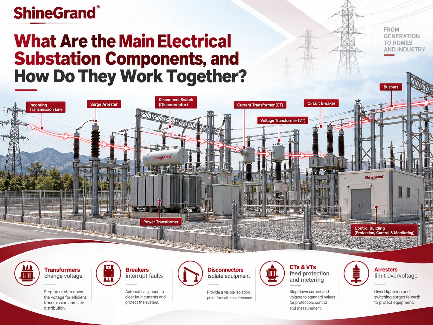
What are the main components of an electrical substation? The essential components of an electrical substation include the following: power transformers, circuit breakers, busbars, disconnectors, current transformers, voltage transformers, surge protectors, protection relays, grounding system, reactive power devices including capacitor banks and reactors, station batteries and auxiliary supply systems, and control, SCADA and communication systems. The transformers change the voltage; the circuit breakers interrupt the faults; the disconnectors provide isolation; the current and voltage transformers assist in measuring; the surge protectors limit overvoltages; and the relays determine when to trip.
Electrical Substation Components at a Glance
It helps to sort electric substation components into three groups before looking at each item in detail.
Primary (high-voltage) equipment
- Power transformers: modify voltage from transmission level to distribution level.
Circuit breakers: automatically interrupt load current and fault current.
Disconnect switches and earthing switches: facilitate isolation and earthing of equipment for maintenance.
Busbars: collect and transmit the power to outgoing and incoming circuits.
Surge arresters: contain lightning and switching overvoltages.
Capacitor banks and reactors: regulate reactive power and voltage.
Fuses: protect small transformers and sub-circuits, mostly in distribution substations.
Measurement and protection equipment
- CTs, or current transformers, reduce current for relaying and metering purposes.
VTs, or voltage transformers, reduce voltage for relaying and metering purposes.
Protection relays are responsible for recognizing faults and sending trip signals to the circuit breakers.
Metering is the process of capturing energy flow for billing and operational purposes.
Control and auxiliary systems
- Grounding systems help safe body and equipment during faults and lightning.
Station batteries and auxiliary power enable working of protection and control after loss of main supply.
SCADA and communication systems allow the operators to monitor and control substation remotely.
Structures, insulators and cables connect everything.
The Essential Electrical Substation Components Explained
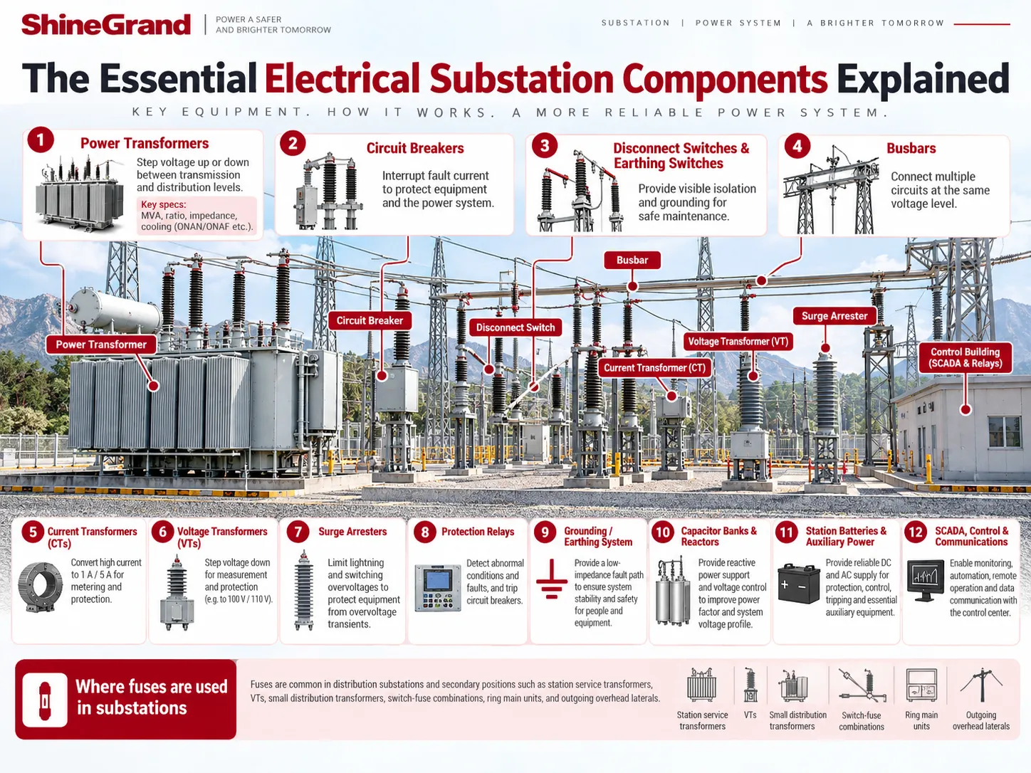
Here is what each of the main electrical substation components does, where it sits and what defines its rating. The illustration below shows the twelve components grouped as primary equipment, measurement and protection, and control and auxiliary systems.
1. Power transformers
The transformer in the power substation is one of the biggest items in cost as well as size. The power transformer increases or decreases voltage for purposes of transmission and distribution respectively. For instance, changing 132 kV to 33 kV is one of the changes done by substation transformers. Moreover, oil immersed transformers are commonly used in big substations and these types of transformers use either radiators or fans for the purpose of cooling. Furthermore, they also consists of on load tap changers for the sake of stabilizing the output voltage of changing load and power supply.
ShineGrand manufactures oil-immersed transformers for substation use, including 110–132 kV oil-immersed transformers and 6–10 kV distribution transformers. For guidance on sourcing, see where to find reliable high-voltage substation transformers.
2. Circuit breakers
The circuit breakers are the only components of the substation that break fault current. In the case of failing equipment of the transmission lines, the fault relay operates to disconnect the circuit breaker and operate the circuit breaker contacts. The circuit breaker operates to stop the electrical arc in the circuit. During high power transmission circuit breakers discharge their current in the cases of immediate successive open-close operation. For those facilities where the operation conditions are quite safe and reliable, the manufacturers are now switch to the SF6 technology which dominates in cases of high power transmission.
3. Disconnect switches and earthing switches
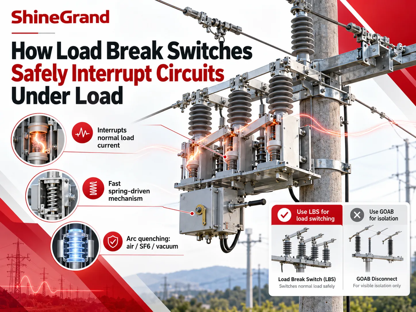
One of the main functions of disconnectors is to create an air gap in the substation equipment when it needs to be repaired. Disconnectors open only after circuit breaker disconnects the electricity supply.Three-phase disconnectors in outdoor substations are usually configured as gang-operated air break (GOAB) switches, installed on the sides of switchgear and transformers. ShineGrand’s guide to GOAB switches explains how they work, and the GW series outdoor disconnectors cover 10–12 kV and 40.5 kV substations.
4. Busbars
The busbar is a conductor made from aluminum tube or bunch of stringed conductors in external yards or copper bars, made from inside switchgears. The bus organizes connections for various lines and feeders operating on the same voltage, and hence the substation design, such as single bus, sectionalized single bus, double bus and breaker and half allows for different flexibility levels when some pieces of equipment are out of operation.
5. Current transformers (CTs)
Current transformers are responsible for conversion of primary current into relatively small secondary current, operating at the level of 1 А or 5 А. Additionally, they also play the isolating function. CTs can be either independent outdoor items or bushing transformers. ShineGrand’s guide to high voltage outdoor current transformers covers ratios, accuracy classes and saturation.
6. Voltage transformers (VTs)
Voltage transformers or PTs are used for reducing voltage inputs down to standard levels.Capacitive voltage transformers (CVTs) become the devices of choice as transmission voltages spiral upwards and allow the coupling of communication signals. For insight on testing techniques, read ShineGrand’s article on how to test a potential transformer.
7. Surge arresters
Surge arrestors save transformers and various equipment from lightning strikes and overvoltage during switching operations, thanks to their ability to conduct the surge directly to the ground while ensuring limited voltage is seen by the equipment. Surge arrestors are fitted at entry points in substations and right near the terminals of transformers. Station-type arrestors are designed to absorb more energy than the distribution type. See ShineGrand’s guide to what a surge arrester is and the station surge arrester range.
8. Protection relays
Protection relays are responsible for taking decisions. They detect issues based on signals obtained from CTs and VTs, including overcurrent, ground faults, line distance faults and differential current present in transformers and busbars, to trip circuit breakers in less than a second. New age relays have the ability to keep records of abnormal events and communicate with SCADA.
9. Grounding (earthing) system
Below every substation lies a grid of cables running horizontally underground and connected to grounding rods, which all the equipment frames, structures, fences and neutral points are connected to. It offers a route of low resistance for the fault and lightning currents to flow and minimizes the step and touch voltages to keep people in safety during the fault. Overhead shield wires protect the area from getting directly struck by lightning.
10. Capacitor banks and reactors
Capacitor banks offer reactive power so that voltage can be stabilized in case of heavy load. On the other hand, shunt reactors act to absorb reactive current on quiet or long lines where voltage spikes are common. Series reactors limit short-circuit current, while static VAR compensators or STATCOMs create a dynamic control of voltage at big substations.
11. Station batteries and auxiliary power
Protection relays, circuit breaker trip coils and control systems must operate normally even when the main power supply fails or disappears due to a fault. A station battery, usually fed with 110 V or 125 V DC power from chargers, is responsible for maintaining this powerful supply.
Station service transformers supply AC needed for lightening, heating, transformer cooling fans and pumps as well as battery chargers.
12. SCADA, control and communications
Control and communication systems provide operators with the information regarding breakers’ positions, measurements and alarms and help operate the necessary equipment. In addition to that, in case of digital substations, merging units and IEC 61850 networks take the place of most copper related wiring between primary equipment and relays.
Where fuses are used in substations
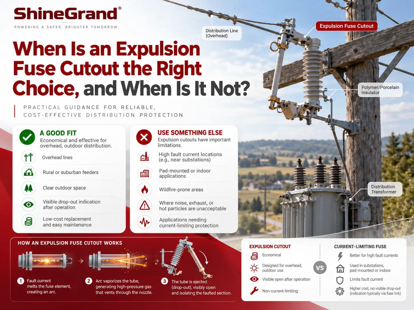
Fuses are not regarded as the key protection type in big transmission substations as breakers and relays perform this task. Nevertheless, fuses can often be found in power distribution substations and various secondary locations: including the protection of its own services transformers and voltage transformers, as well as small transformers and switch-fuse units and ring main units. On the overhead lines leaving a substation, fuse cutouts protect laterals and pole transformers.
How Do Electrical Substation Components Work Together?
Observing the electricity journey in a classic step-down substation (132/33 kV) indicates how the various units forming part of an electric substation work together. A simplified version is considered, as the more exact order and configuration varies in accordance with the relevant single-line diagram specific for the examined station.
1.The power line completes a journey of 132 kV before entering the station. Surge arresters situated along the line capture powerful surges entering the station.
2.The line then passes through a line disconnector that ensures isolation of the line in the process of servicing, in addition to earthing switches located on the line side.
3.CTs and VTs are used to assess both current and voltage readings of the line, thus feeding information to measuring devices and protective relays.
4.A circuit breaker serves as a connection between the line and power station, tripping in case protection devices pick up a malfunction.
5.The line is connected to the bus at 132 kV, thus allowing for connection of other lines into the simpler bus arrangement.
6.A disconnector and a circuit breaker control the flow of electricity going to the power transformer, which performs its own surge arrest and differential protection through CTs, located on both sides of the transformer.
7.The 33 kV side of the transformer connects to the line through the circuit breaker to connect it with a bus at 33 kV.
8.Third branch lines include 33-kV feeders provided with their own respective circuit breakers, CTs, and sensors.
9.From the other point of view, the grounding system and SCADA play the important roles of supporting power station control and security systems.
There is a certain function for each of the operational units. Relays control the current flow, circuit breakers switch off; disconnectors isolate the lines, CTs and VTs make readings; arresters limit voltage levels. If one of the units is not working properly or has inappropriate power characteristics, the functioning of the station is compromised.
What Are the Four Types of Substations?
There are many methods to classify substations on various bases but for the purpose of their functions; there are four main types;
Transmission Substations – make connections between transmission lines and convert high transmission voltages, like 400/132 kV. A type of transmission substation is the step-up station located at power plants where the generator voltage is increased at the time of transmission.
Distribution Substations– bring down transmission or sub-transmission voltages to distribution level voltages like 33/11 kV and supply local networks.
Switching Substations – connect and switch lines at similar voltage levels of the connections without conversion they help increase flexibility and reliability in operation.
Collector Substations- collect electricity from different power generating stations like solar or wind plants and convert it for power line connection.
Other classifications comprise converter substations for HVDC operations, mobile substations for temporary or emergency operations and classifications according to their structure such as outdoor air-insulation, indoor type, gas-insulation type, and pole-mounted type. For collector substations in renewable projects, ShineGrand’s guide on how solar farms work shows where they sit in the plant.
Substation vs Switchyard Components
Switchyard is the section pertaining to high-voltage switching at a plant/substation. It generally consists of main components such as busbars, circuit breakers, disconnectors and ground switches, CTs and VTs (or CVTs), surge arresters, traps and communication tools, gantries and support framework, insulators and ground systems. A switchyard does not have to undertake any transformation; usually, at a power station generator, the step-up transformer is placed next to it. A substation is the larger term and usually includes transformers and switching systems.
How Substation Components Change with Voltage Level
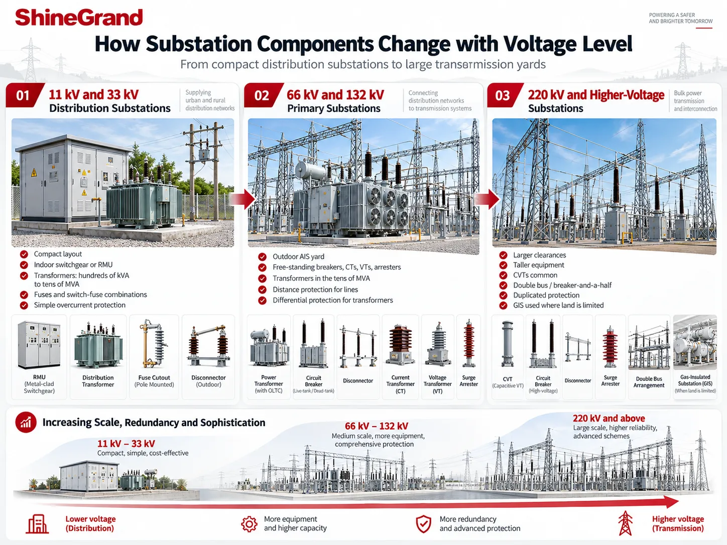
The basic functions stay the same at every voltage, but the equipment that performs them changes as voltage rises: clearances grow, switching moves from indoor switchgear to outdoor yards or gas-insulated designs, and protection becomes more sophisticated and more redundant.
11 kV and 33 kV distribution substations
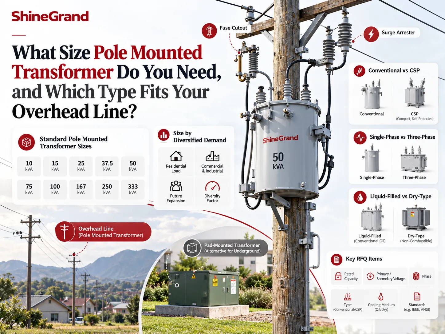
The structure of these substations is compact. In medium-voltage switchgear, switching is obtained in metal enclosed switchgear or in ring main units rather than open-air installations. If we talk about power, the rating is from a several hundred kilovolt-amperes to some tens of megavolt-amperes. The use of fuses and combination of switches and fuses together with simple overcurrent protection is prevalent. The substation located in an isolated area might use small facilities with pole-mounted equipment, fuse cutouts and outdoor disconnectors.
66 kV and 132 kV primary substations
At these voltages, air insulating installations are used, involving free-standing breakers, disconnectors, transformers (CTs) and voltage transformers (VT) on steel supports outdoors. The protection system is very complex here since it includes distance protection from faults and differential protection for transformers. Power transformers usually come with power ratings of the order of several tens of megavolt-amperes, with on-load tap changers.
Transmission substations working at voltage levels of 220 kV and above
The design of transmission substations is more complicated calling for larger clearances and installation of higher devices, as well as CVTs instead of inductive VTs and installation of more redundant circuits (double-bus or breaker-and-a-half schemes). The protection is made redundant and communication aided protection systems are used.
Air-Insulated vs Gas-Insulated Substation Components
Similar functions can be achieved using different techniques:
In the case of air insulation substations, air is employed as an insulation medium in addition to outdoor components being mounted on the structures. Although building air-insulated substations is cheaper and inspection as well as expansion is much simpler, it requires large areas for the construction.
Gas-insulated substations are houses the switching equipment such as isolators, circuit breakers, busbars, and CT inside grounded metal casing filled with SF6 or other gas. Although the construction of GIS requires less area and the facility is protected by the environment and pollution, the cost of construction is higher than that of AIS.
ShineGrand’s article on GIS for data centers looks at how much space gas-insulated designs can save.
What Are the Four Main Parts of a Transformer?
Transformer is an important component of a substation. Its critical parts are listed below:
1.Core. It is made of laminated electrical steel and allows the magnetic field to flow through the windings.
2.Windings. The copper or aluminum coils transferring the current and allowing determining the voltage relation.
3.Insulator. It is made from paper, pressboard and insulating oil and separates the windings and core.
4.Tank. It is a steel structure made to place the core, windings and oil.
In addition to the critical parts, there are additional parts, such as bushings, conservator or the closed expansion unit, tap changer, cooling radiators and fans, Buchholz relay, pressure relief systems and temperature systems.
Common Problems with Substation Equipment
- Overheating of transformers, aging of the insulation, ingress of moisture in oil, and wear and tear of the tap changer are detected by analysis of the dissolved gases in oil and oil testing.
In circuit breakers slow operation, leakage of SF6, wear of contacts, and faults in the mechanisms are monitored.
Malfunction of disconnectors refers to problems with the seized mechanisms, misaligned actuating device, and overheating of the contacts.
The failures in CTs and VTs comprise insulation failure, saturation which disturbs operation of protection, and problems in wiring.
The major problem with surge arresters is moisture ingress which causes their failures.
In connections high resistance and hot spots are discovered by means of infrared thermography.
The above mentioned problems can turn into failures, and only regular inspection can avert that.
Substation Equipment Checklist for EPC Contractors and Buyers
While giving specifications or requesting quotations for electrical substation components, it is important to state:
– The system voltages, frequency, and grounding.
– Transformer ratings in MVA or kVA, voltage ratio, vector group, impedance, cooling, and tap changer.
– The short-circuit level for every voltage, setting the ratings for the breaker, disconnector, busbar, and CT respectively.
– Insulation coordination of a surge arrester and BIL ratings of the equipment.
– Busbar arrangement along with the rated currents.
– Protection, metering, and control requirements including CT and VT ratios and their accuracy.
– Site conditions such as altitude, temperature, pollution level, seismic zone, and available space.
– The applicable standards including IEC 62271, IEC 60076, and IEC 61869 or the series of IEEE standards like C37 and C57.
– Factory acceptance tests, type test reports, and documentation.
ShineGrand Equipment for Substations
ShineGrand Electric does not supply every component of a substation, but it manufactures several of the key primary items:
- Power and distribution transformers, including 110–132 kV and 6–35 kV oil-immersed units.
- Outdoor disconnect switches, such as the GW4-40.5/630 and GW5-40.5/1250 for 33–35 kV substations.
- Surge arresters, including station-class units.
- Fuses and fuse cutouts for distribution substations and outgoing overhead lines.
If you are planning a substation, send ShineGrand your single-line diagram or equipment list to confirm which items can be supplied.
Frequently Asked Questions
What are the typical equipment components of a substation?
Typical equipment found in a substation consists of power transformers, circuit breakers, disconnector and earthing switches, busbars, CTs and VTs, surge arresters, protection relays, earth system, capacitor banks or reactors, station batteries and auxiliary services, SCADA and communication systems.
What are the four types of substations?
By function, substations are commonly grouped as transmission substations, distribution substations, switching substations and collector substations. Converter substations for HVDC and mobile substations are additional specialized types.
What are the typical components of a switchyard?
A switchyard usually consists of busbars, circuit breakers, isolators, earth switches, current and voltage transformers (CVTs), surge arresters, control communication devices such as line traps, gantries, and support systems, as well as insulators and grounding grids.
What are the four main parts of a transformer?
The four main parts are the core, the windings, the insulation (including insulating oil) and the tank. Bushings, a tap changer, cooling equipment and protective devices are important accessories.
What is the most important component in a substation?
The power transformer is typically the priciest and most crucial component of the power plant, since it is responsible for voltage transformations and replacing it is not a quick process. However, the entire substation will be able to operate safely only when transformers, circuit breakers, relay devices, and grounding work together.
What is the difference between a disconnector and a circuit breaker?
A circuit breaker can interrupt load and fault current, usually on a signal from a protection relay. A disconnector cannot interrupt load; it is opened after the breaker to provide a safe, visible isolation gap for maintenance.
Why are CTs and VTs used in substations?
CTs and VTs reduce high currents and voltages to small standard values that meters and protection relays can safely use, and they isolate those low-voltage circuits from the high-voltage system.
What components are used in a 33kV substation?
An ordinary 33 kV substation is made up of incoming line or cable terminations, surge arresters, disconnectors, 33 kV circuit breakers or switchgear, CTs and VTs, busbars, one or more 33/11 kV transformers, 11 kV switchgear for outgoing feeders, protection relays, a station battery, auxiliary transformer and grounding system.
References
- Electrical Engineering Portal — Substation Elements. Graphic symbols and functions of substation equipment and busbar arrangements.
- IEC 62271, IEC 60076 and IEC 61869. International standards for high-voltage switchgear, power transformers and instrument transformers.
- IEEE C37 and C57 series. North American standards for switchgear, protection and transformers.
- IEEE 80 — Guide for Safety in AC Substation Grounding. Design of substation grounding systems.
- Wikipedia — Electrical substation. General background on substation types and equipment.
Planning a Substation Project?
Understanding the main electrical substation components and how they work together is the first step to specifying a safe and reliable substation. For transformers, outdoor disconnect switches, surge arresters and fuses, contact ShineGrand with your single-line diagram, voltage levels and equipment ratings for a quotation.